Attic Apartment
Clean-up and prep
The job began by emptying the attic the residual junk that tends to accumulated in attics. We then removed the existing tongue and groove finish ceiling and stored it for future use and then removed the underlying foam sheet material (a makeshift weather barrier?) to expose rafters. We then cleaned the area between the rafters of spiderwebs, residual construction waste from the roofing process, and all manner of other dirt, and cleaned the concrete floor slab with a shopvac.
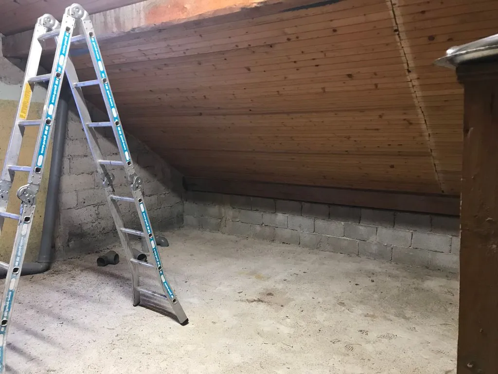
The initial state of the project after emptying the attic: a concrete slab floor, and a tongue and groove finish ceiling over uninsulated rafters.
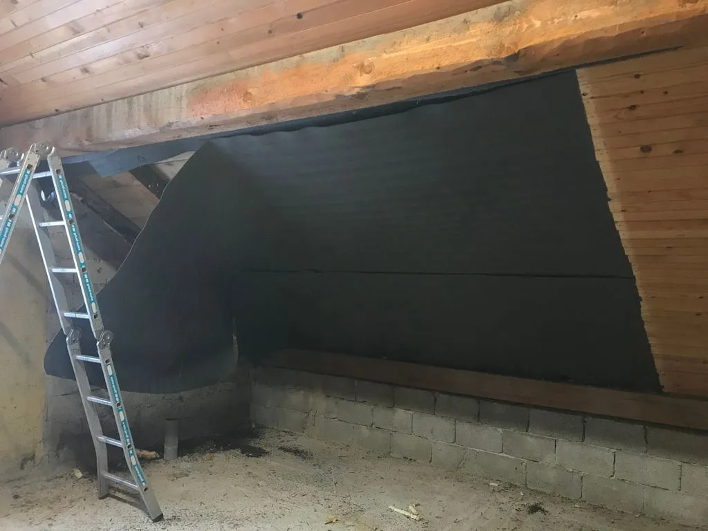
The finish ceiling removed, showing the foam-like sheet material placed between the finisih ceiling and rafters (perhaps this was a makeshift air or moisture barrier?).
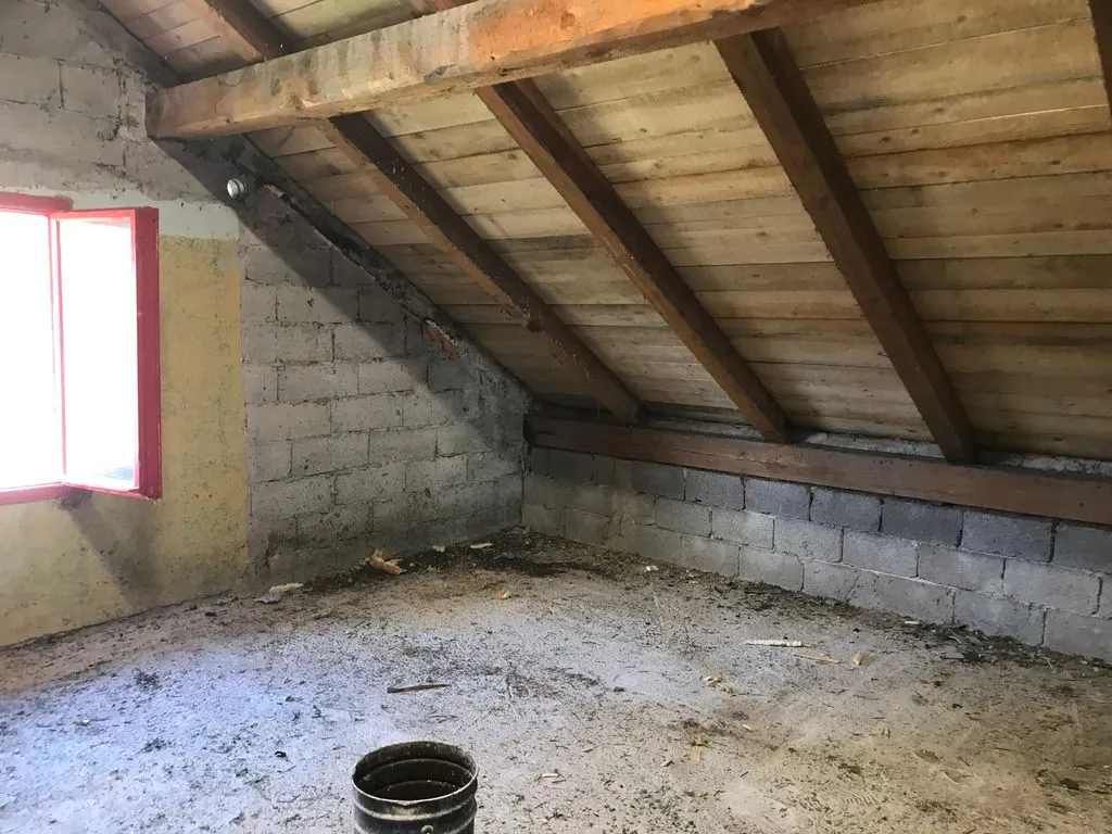
The bare, uninsulated rafters, with the exterior board sheathing visible above the rafters.
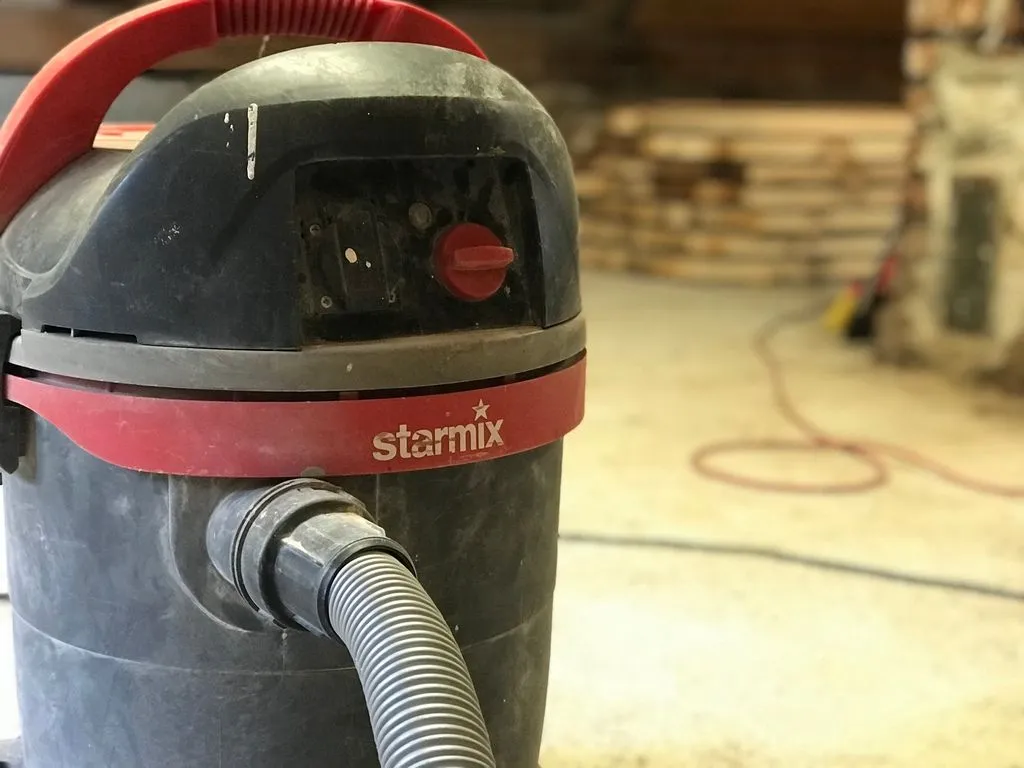
The StarMix shopvac used to clean the floor.
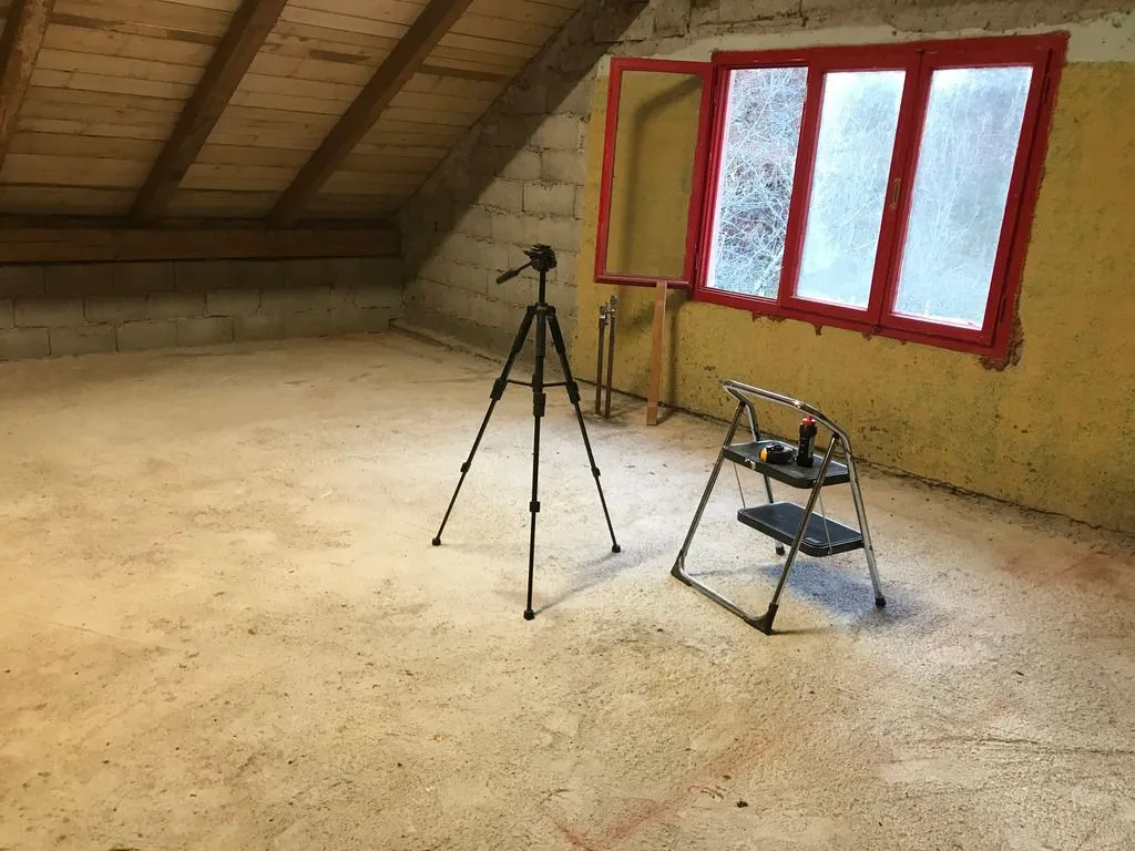
The cleaned floor after finishing the finish ceiling removal. The tripod will later hold a laser level.
Subfloor
The subfloor is built on a substructure of sleepers fastened to the concrete floor slab. The sleepers are leveled with a laser level and shims, creating a level, planar surface above the slab (which was rather roughly poored and is far from planar!). Polyurethane foam under the sleepers provides additional support from below. A perpendicular layer of slats placed across the sleepers gives the floor improved elasticity/bounciness, making the floor more pleasant underfoot. The grid was later covered with tongue and groove OSB subfloor.
In hindsight, building the subfloor substructure this early was a mistake. We should have built it only after completing masonry work on walls and insulating the ceiling, in which case the subfloor wouldn't have gotten as dirty from construction waste nor gotten in the way underfoot.
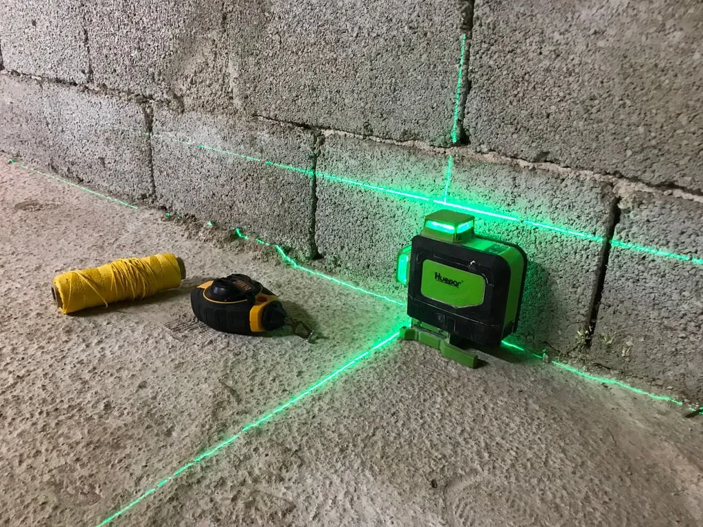
We used a laser level and chalkline to lay out the grid's position on the floor slab.
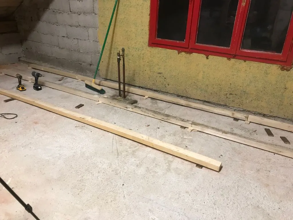
The first sleepers being attached to the concrete floor slab. The sleepers are attached with the Slovene equivalent of TapCon screws ("Turbo vijaki") drilled directly into the concrete, with shims used to level the sleepers. Polyurethane spray foam under the sleepers provides additional support.
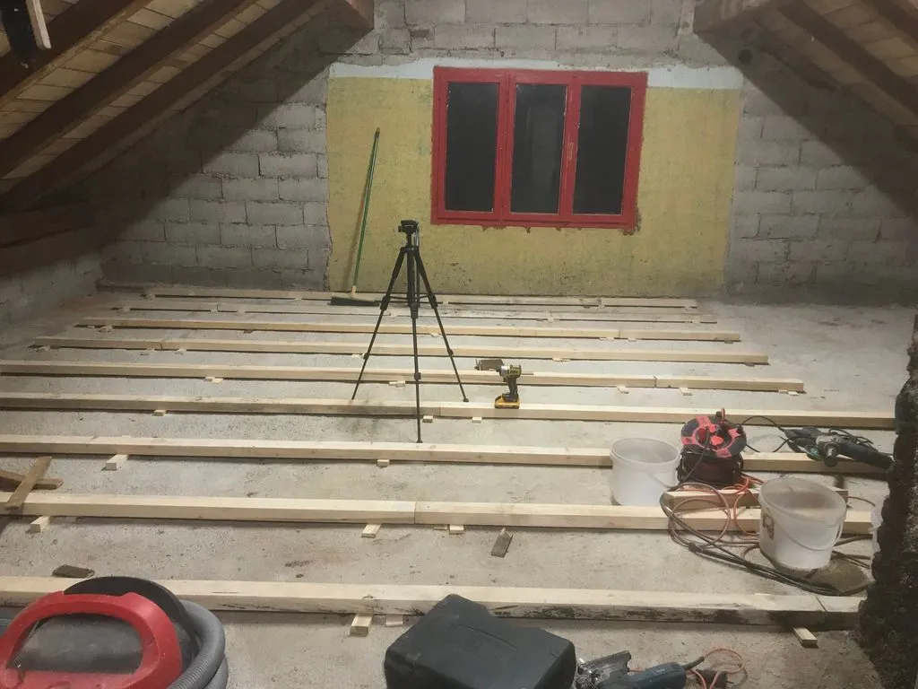
Nearing completion of the sleepers. The tripod held the laser level that we used to level the sleepers.
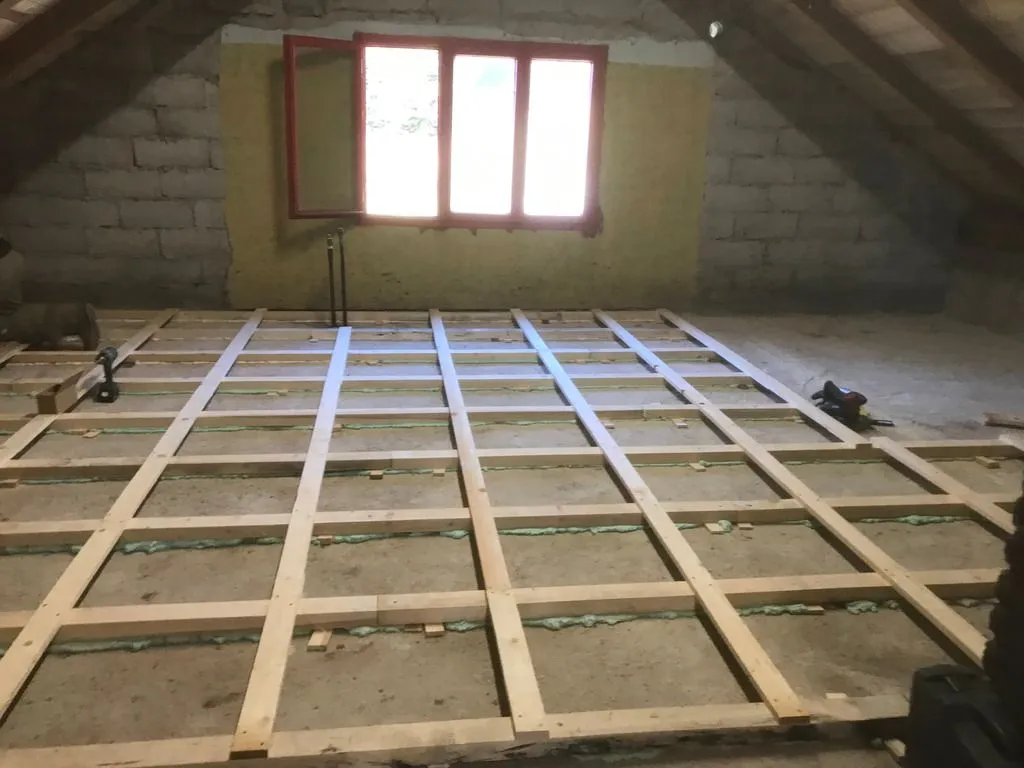
The completed subfloor substructure, with slats placed perpendicularly across the sleepers for added springiness. Spray foam has been added under the sleepers for additional support from below.
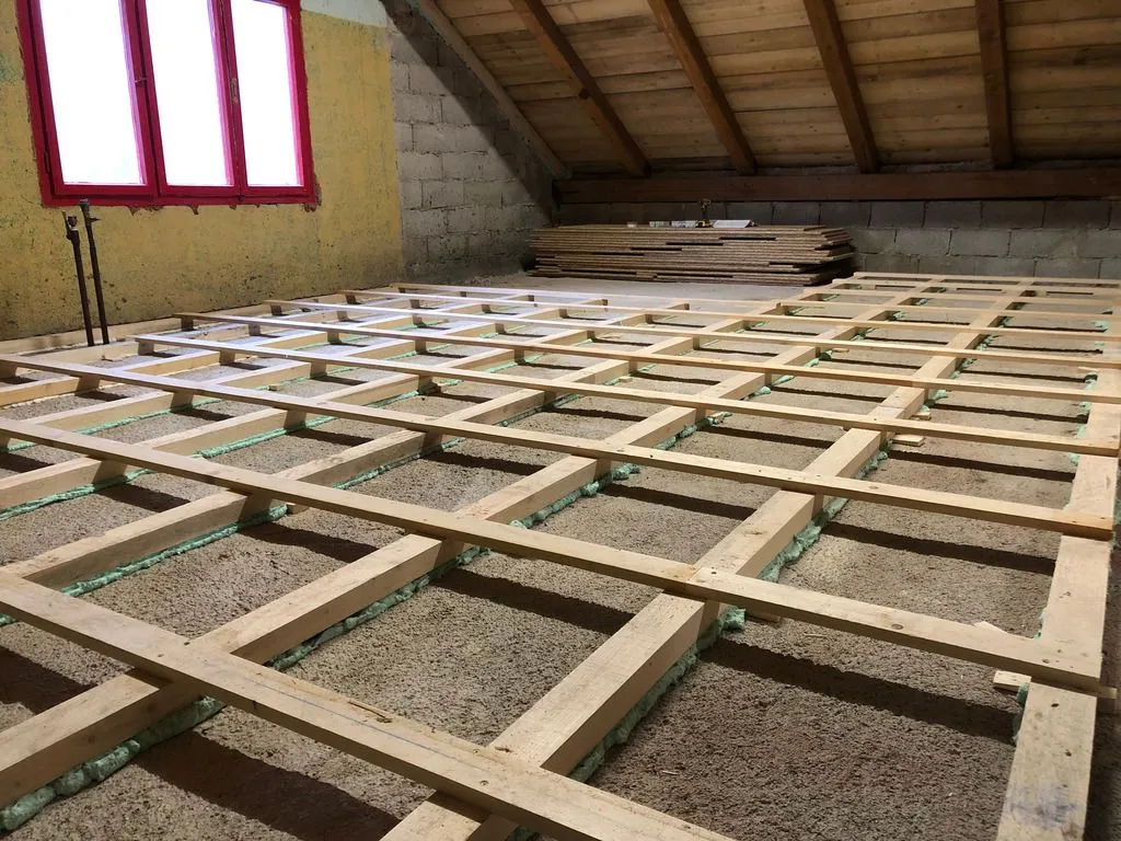
Perspective image from floor height showing the subfloor's grid substructure.
Insulating the roof
The roof is insulated with 200 mm of rock wool (Isover PLE MAX, made by Saint Gobain, with thermal conductivity 0.037 W/(m K)). The rock wool is placed in two layers—one 150 mm between the rafters, with an additional 50 mm placed continuously over the rafters to eliminate thermal bridging. The rock wool between the rafters is nominally attached with a friction fit, but we also used polyurethane spray foam as an adhesive for insurance.
Details: the rafters are 140 mm deep, and our building materials supplier did not have 140 mm thick rock wool in stock to match the depth of the rafters. We worked around this by placing 150 mm of rock wool (the closest match to 140 mm) between the rafters (the 150 mm layer was made in turn of separate 100 mm and 50 mm layers, because 150 mm was also not in stock), then furred out the rafters with 10 mm of XPS, to match the depth of the 150 mm insulation.
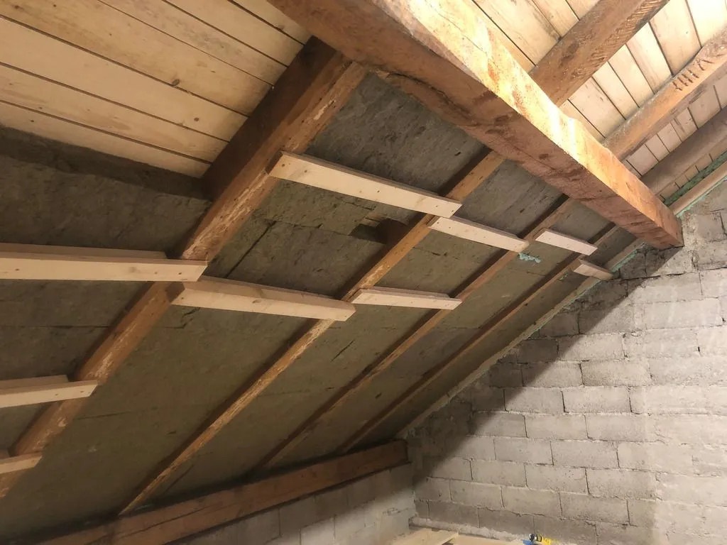
The first layer of rock wool batts (100 mm thick) going in between the rafters. The boards temporarily hold the rock wool batts in place until the polyurethane adhesive on the back cures.
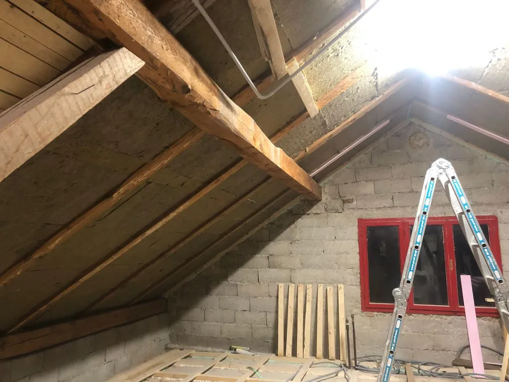
The first layer of rock wool continuing up the ceiling.
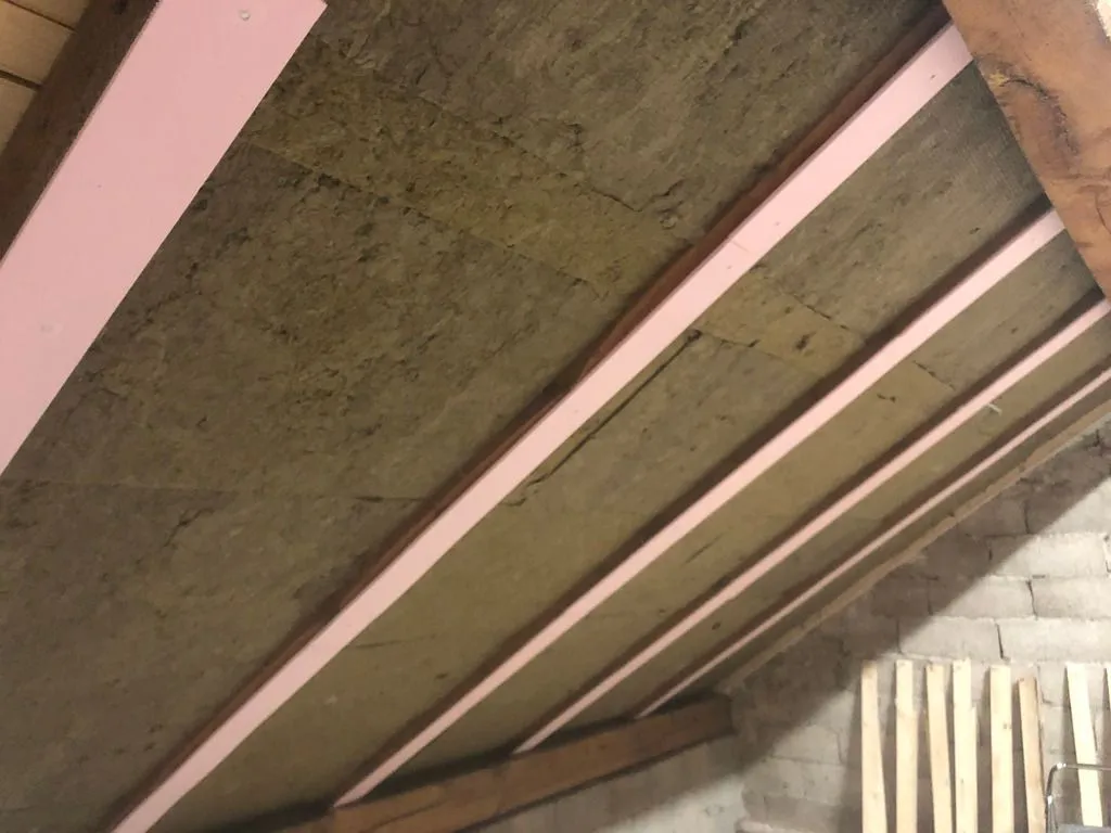
We furred out the 140 mm rafters with 10 mm of XPS to match the final thickness of the rock wool; besides equalizing depths of rafters and insulation, the XPS has the additional benefit of decreasing thermal bridging.
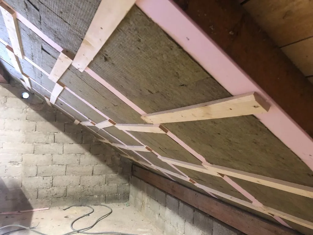
The second layer of rock wool batts (50 mm thick) placed between the rafters, flush with the XPS furring over the rafters. The wooden boards temporarily hold the batts in place until the polyurethane adhesive on the back cures (the adhesive supplements the friction fit).
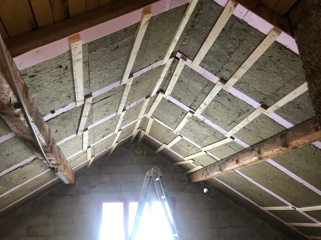
The second layer of rock wool batts continuing up the ceiling.
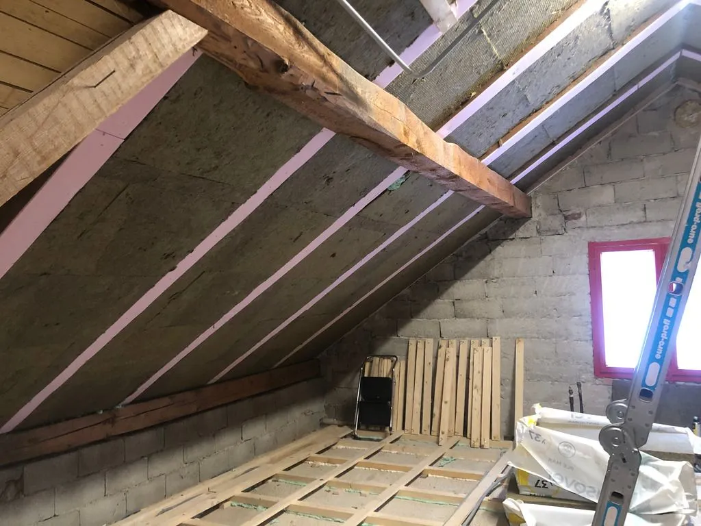
The boards removed after the adhesive has cured.
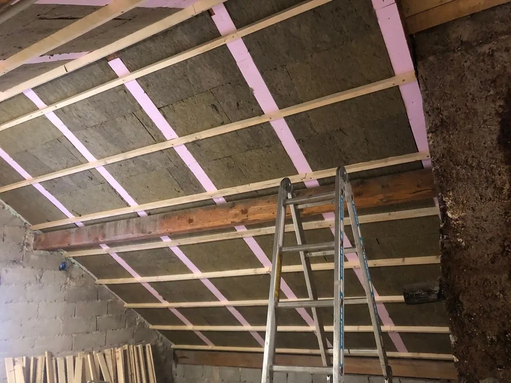
A grid of 50 mm thick wooden cross battens placed over the rafters will hold the final layer of rock wool in place.
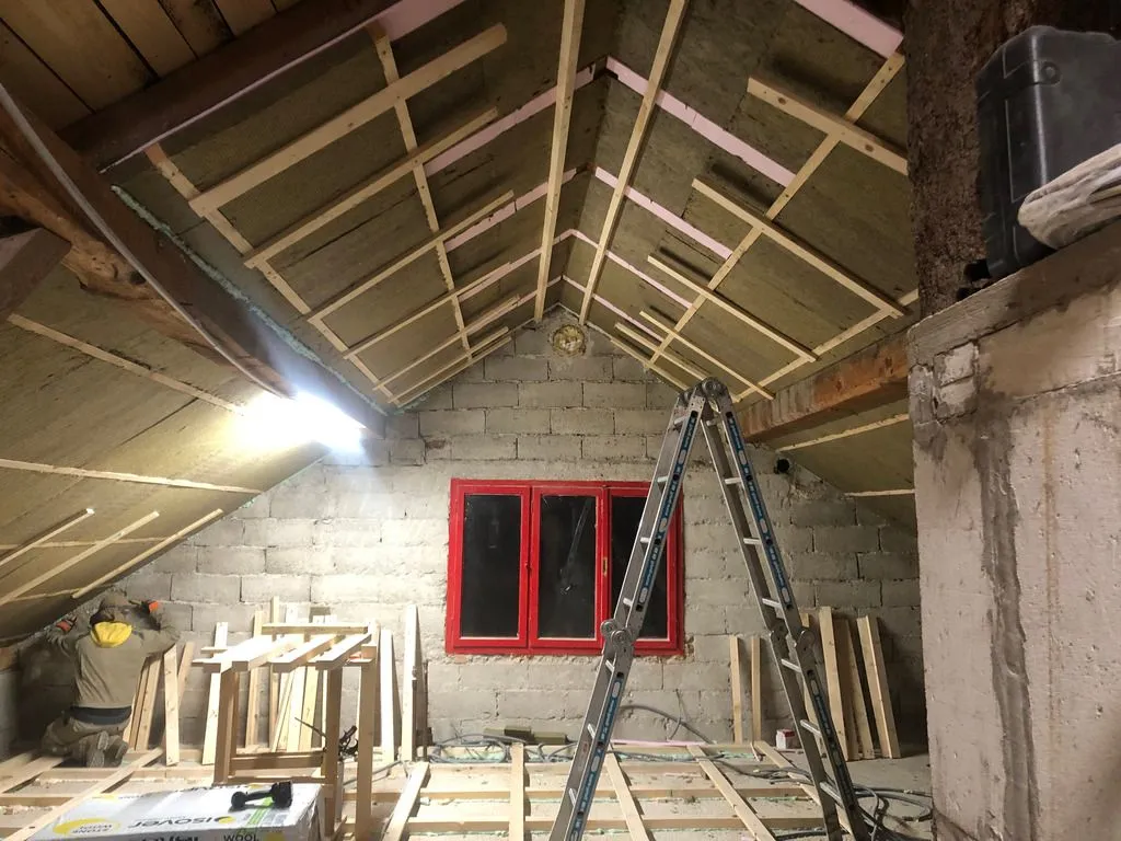
The final layer of rock wool (50 mm thick, placed continuously over the rafters) making its way up the ceiling.
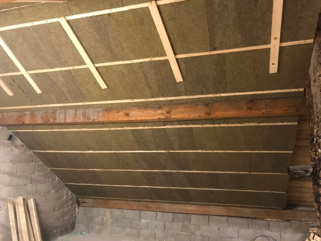
Ditto
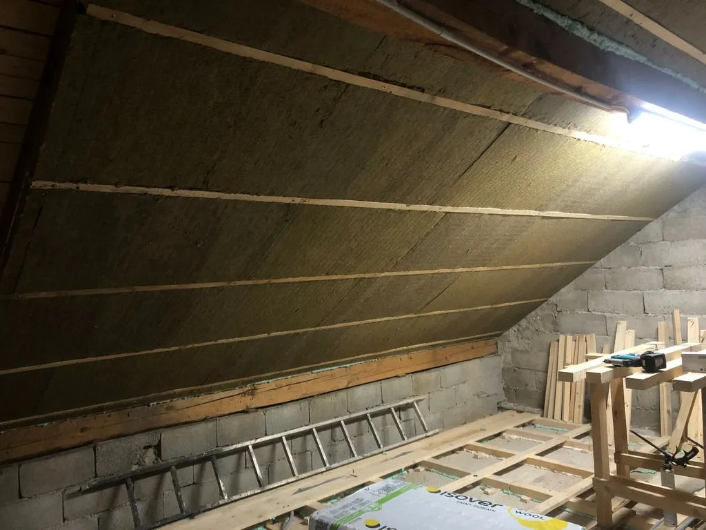
The final layer of rock wool installed. This layer is placed continuously over the entire surface of the ceiling, eliminating thermal bridging through the rafters.
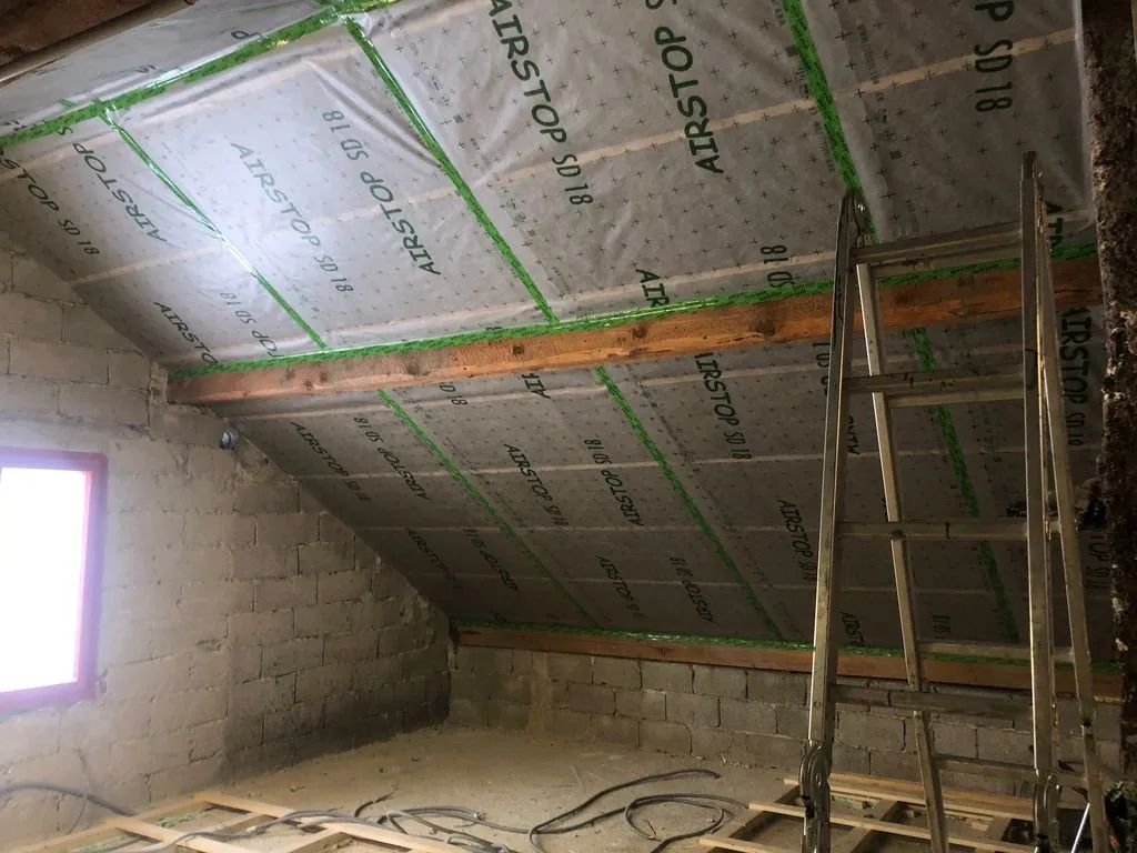
The vapor barrier placed over the insulation, with seams taped. The roof is now ready for the finish ceiling.
Multipor part 1: North and South walls
We insulated the exterior walls with 200 mm of an insulative masonry material called Multipor made by the Slovenian company Xella Porobeton, placed in two wythes (layers), to the inside of the existing loadbearing walls, which are made of concrete block (CMUs).
Multipor is similar to aerated autoclaved concrete, just lighter, softer, more insulative, and nonstructural. It is loosely reminiscent of pumice and has a thermal conductivity of 0.045 W/(m K) (just slightly less insulative than low-quality glass wool, i.e. excellent for a masonry material). It is vapor permeable and (unlike mineral wool) insensitive to water vapor, and is meant to be used without an interior vapor barrier.
Multipor is laid with a mortar-like adhesive like regular aerated autoclaved concrete blocks, and finished with a base coat of mortar embedded in a fiberglass mash, followed by a trowelled finish coat (similar to standard lime-cement render). It is soft and can be easily cut with a hand saw.
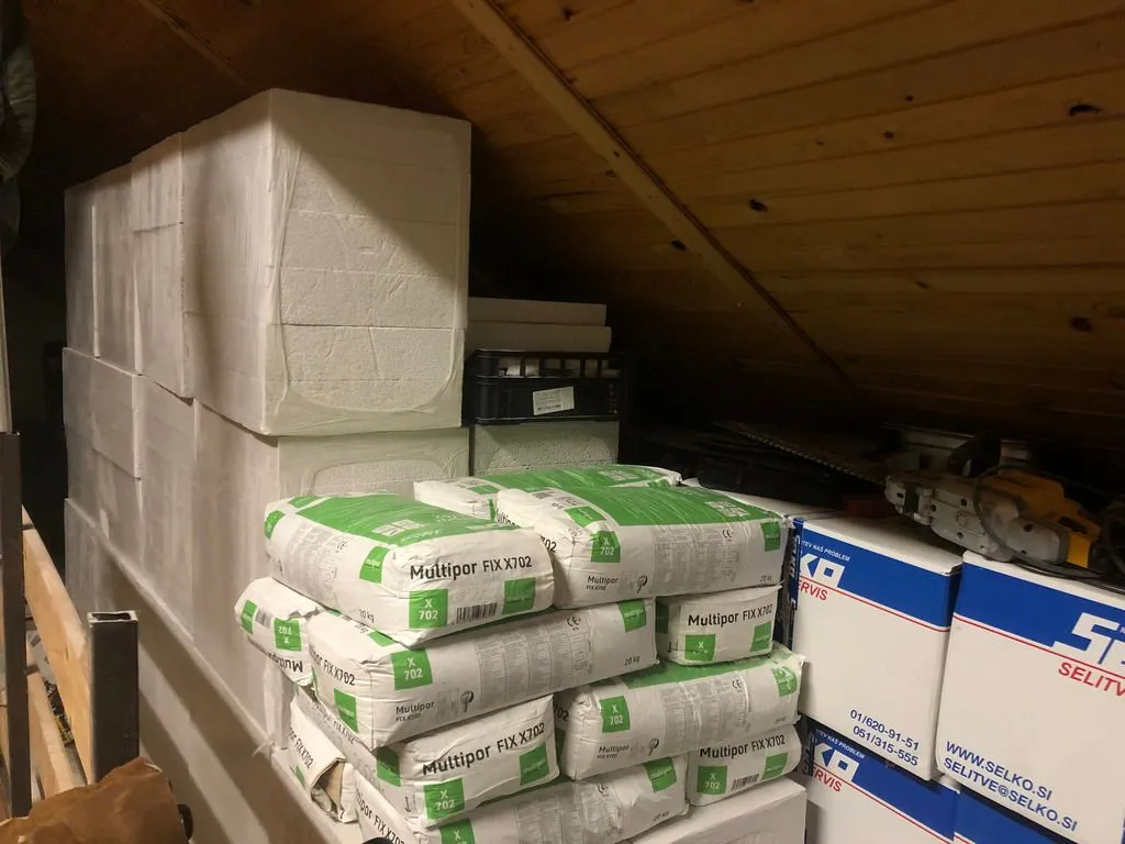
The Multipor blocks and adhesive mortar used to bind them.
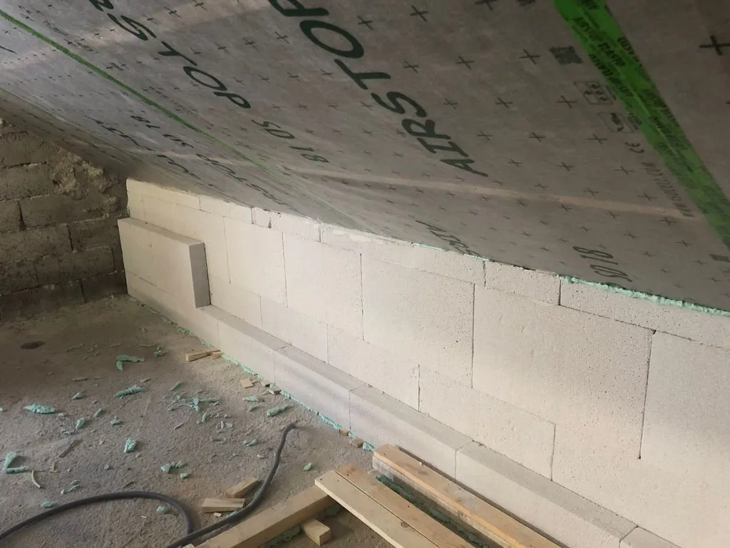
The second layer of Multipor being installed along the south wall. We installed two 100 mm layers for a total thickness of 200 mm.
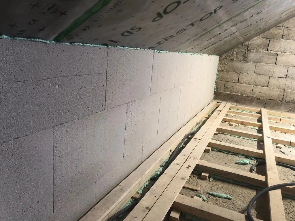
The completed Multipor installation along the south wall.
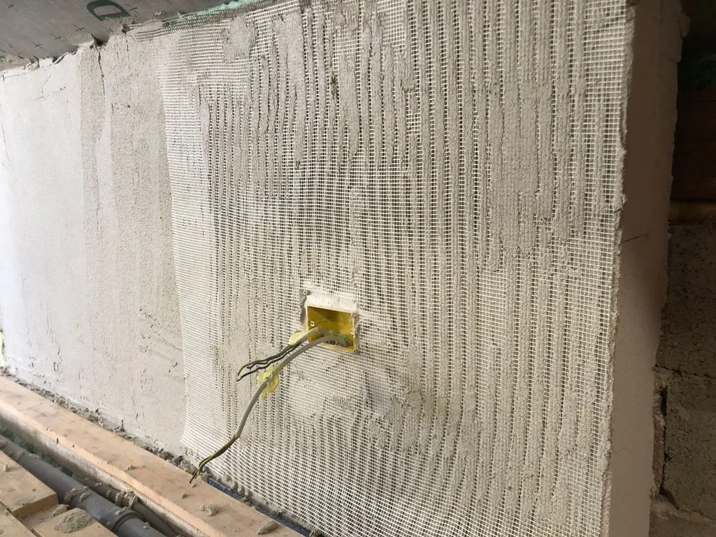
The Multipor blocks are finished similarly to how the process for rendering a masonry wall — first with a base coat of mortar embedded in fiberglass mesh, followed by a trowelled-on finish coat.
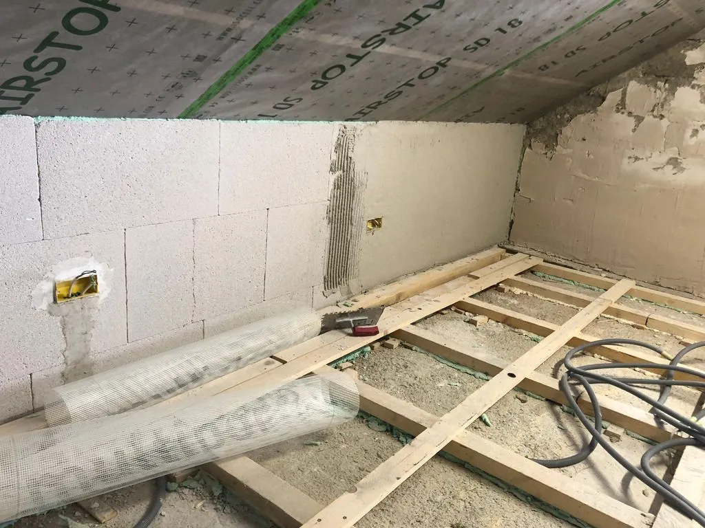
The base coat progressing along the south wall.
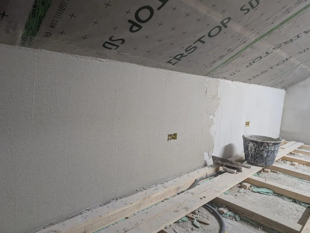
The finish coat progressing along the south wall.
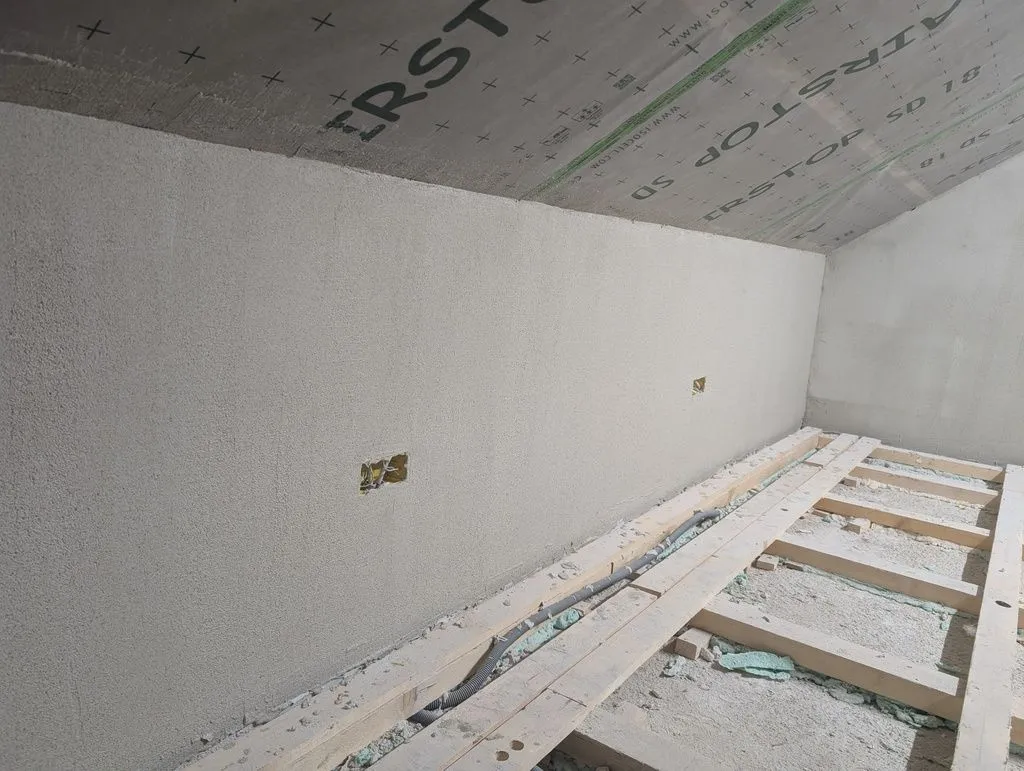
The finished south wall, which will later be painted.
Plumbing rough-in (subcontracted)
Plumbing and heating was the only portion of the job we subcontracted—I had neither the experience nor tools required for the job. We installed supply lines for cold and hot water, drain/waste pipes for a future bathroom, and supply and return lines for central heating with radiators. The water supply and heating lines are made of a material called Aluplast, which is similar to the PEX tubing used in the USA, but with an additional thin aluminum layer around the polyethylene for added mechanical strength. The drain lines are polypropylene (similar to the PVC DWV lines used in the USA).
We ran the supply and drain lines up through the concrete floor slab from the downstairs bathroom (the attic bathroom was intentionally placed over the existing downstairs bathroom to simplify plumbing runs). Heating lines had already been conveniently run to the attic, so we simply hooked into the existing lines.
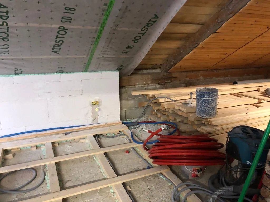
Supply lines (made of Aluplast, similar to the PEX used in the USA) come in large coils, conveniently coming in both a red and blue color to indicate hot and cold lines.
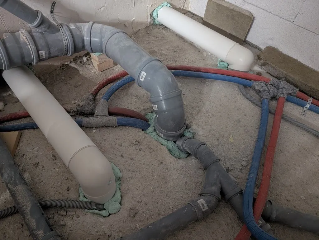
We ran the main drain and supply lines from the downstairs bathroom through the floor slab.
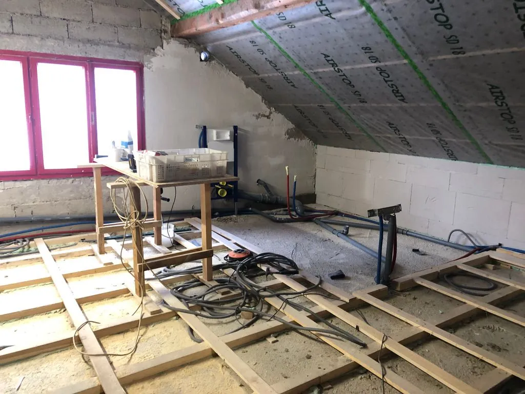
The far corner will hold the bathroom—you can make out the drain lines on the floor for the future bath and sink. (The tubing in the foreground is electrical conduit, unrelated to the plumbing job.)
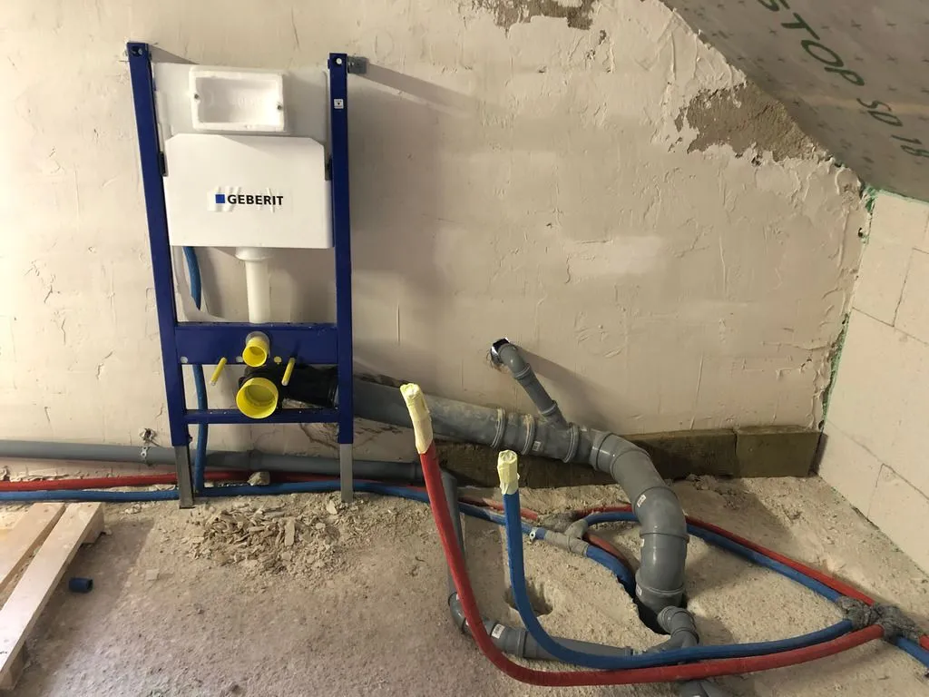
The drain and supply lines for the toilet and bath. The Geberit piece is the substructure that will hold the suspended toilet.
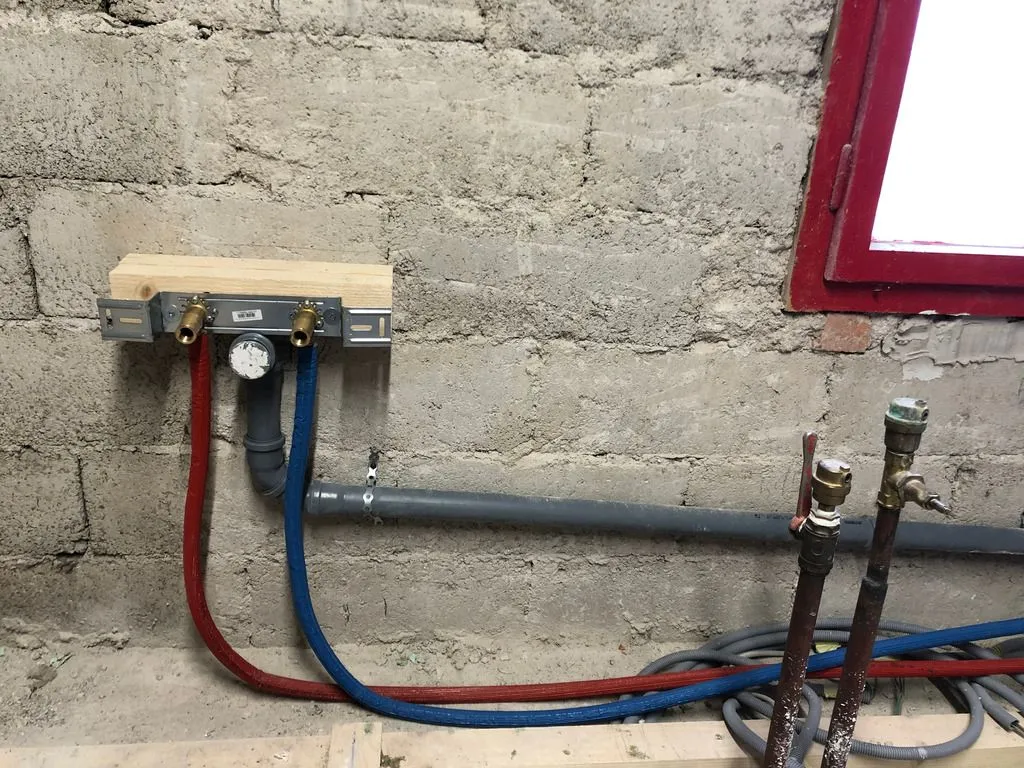
Drain and supply lines for a future kitchenette.
Leveling the west wall (prep for Multipor)
Aside: a lime-cement render would probably have been preferable to the gypsum-based compound. Gypsum can soften in contact with water or weather, while lime-cement render is more robust and arguably more compatible with the concrete block. But we had the gypsum-based compound on hand, and given that it is inside, protected from the elements, it should work just fine. It is also a bit easier to apply and work than lime-cement render.
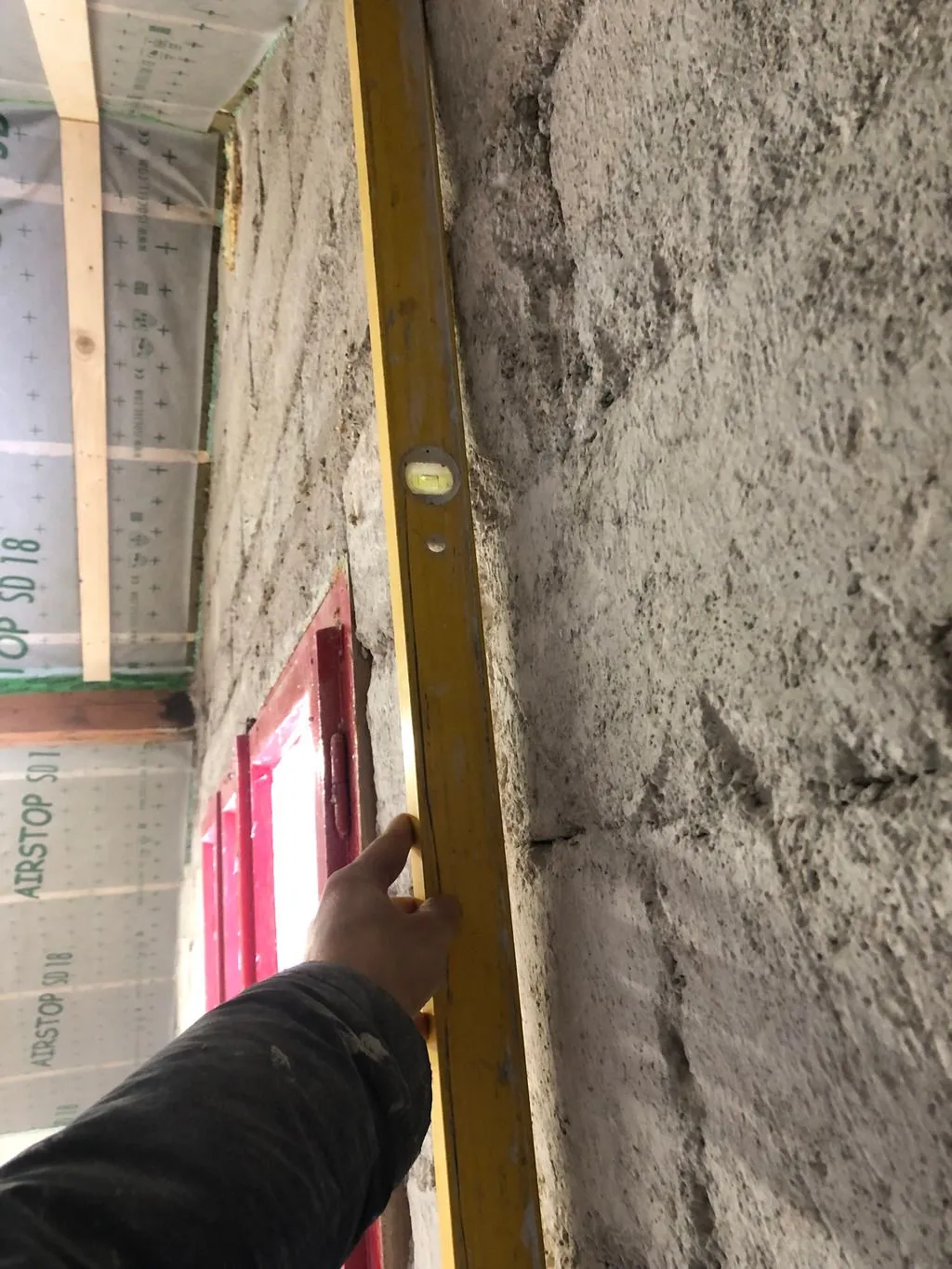
The existing wall is bowed outward—note the large gap under the straight level. We leveled this bow so as to create an approximately planar surface before applying Multipor
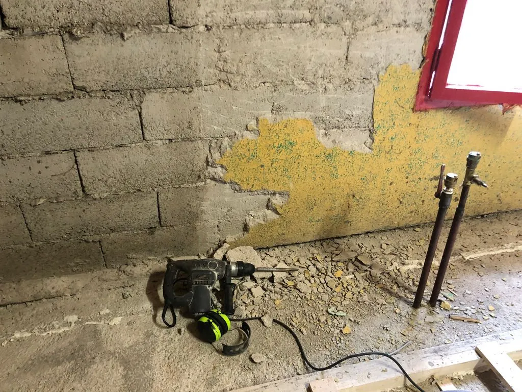
Prep work: there was an unfinished, crumbling layer of render on the west wall around the window, which we first removed with a hammer drill before addressing the bow in the wall.
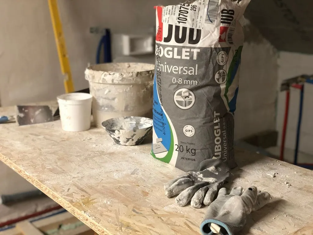
We leveled the wall with a gypsum-based leveling compound, which comes in dry form and is mixed with water to a workable consistency.
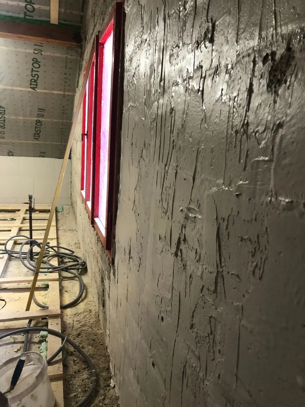
The leveling compound is applied with a trowel—this is the base coat—more coats will follow.
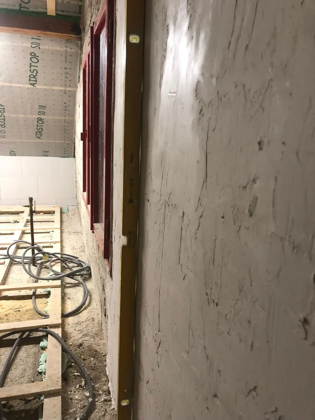
The wall after rough leveling—note that the gaps under the straight level are now minimal compared to the original state.
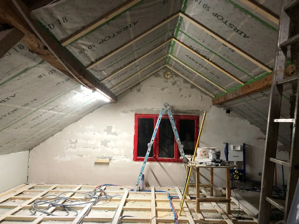
The now mostly-planar west wall, ready for application of Multipor blocks.
Multipor part 2: West wall
Like the north and south walls, we covered the west wall with 200 mm of Multipor, an insulative masonry material. For more on Multipor, see part 1, covering the north and south wall installation.
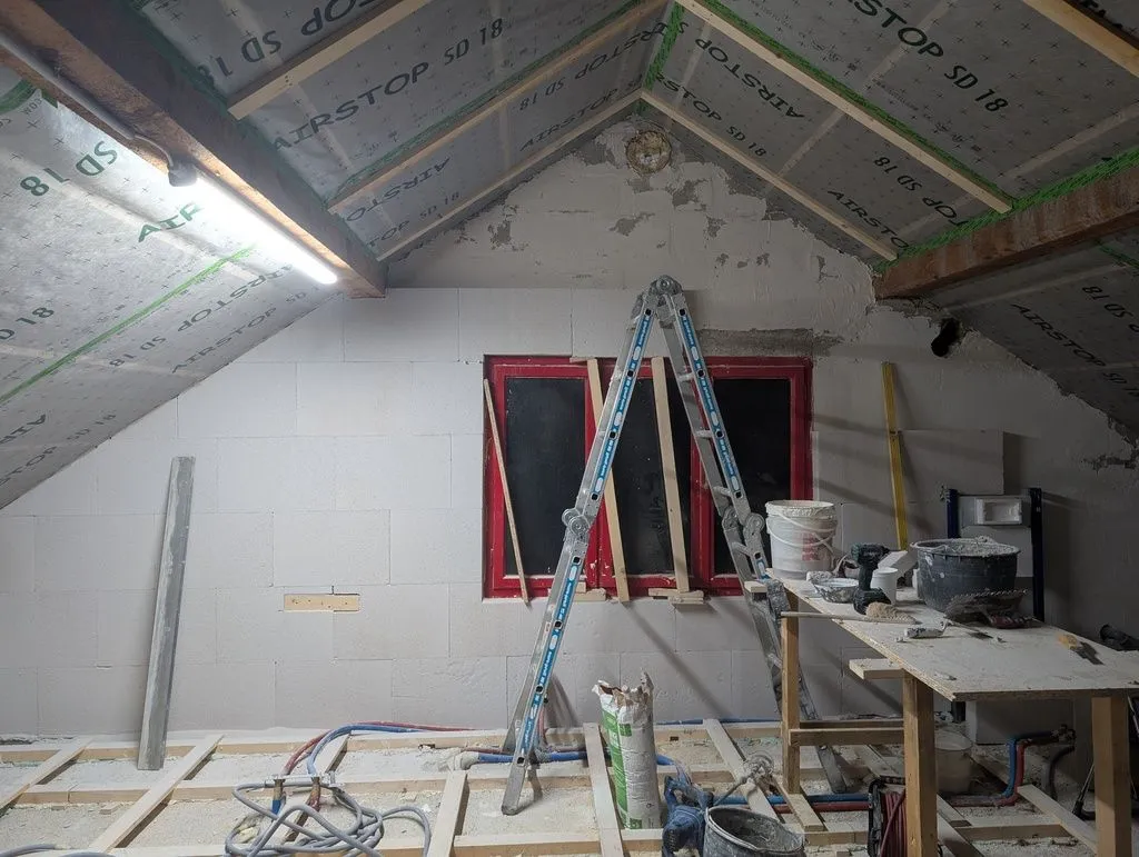
The first layer of Multipor blocks progressing up the wall.
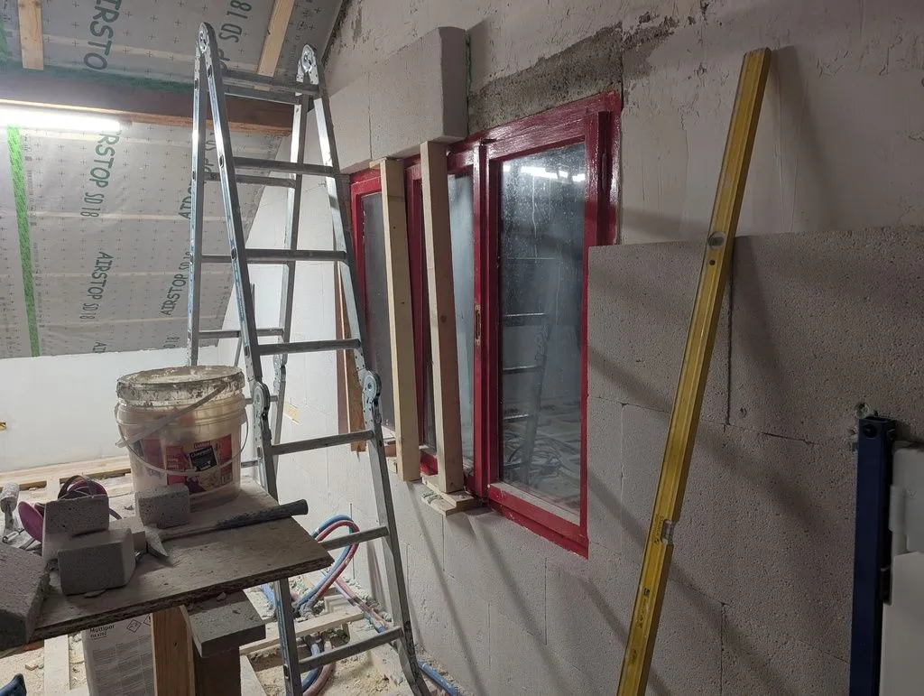
We used wood studs to temporarily support the Multipor above the window until the adhesive cured. The Multipor is light enough that no lintel is needed.
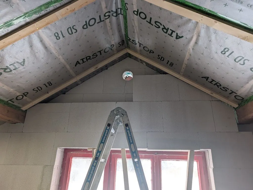
The second layer of Multipor making its way up the towards the ridge.
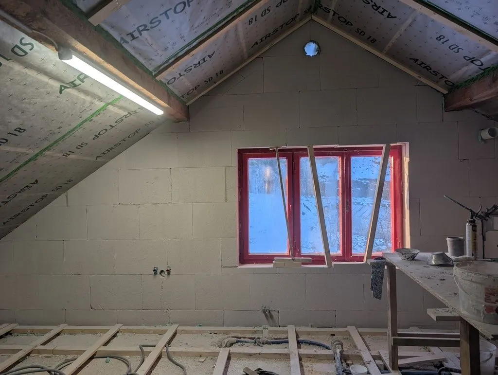
The second layer of Multipor freshly installed, with adhesive still curing.
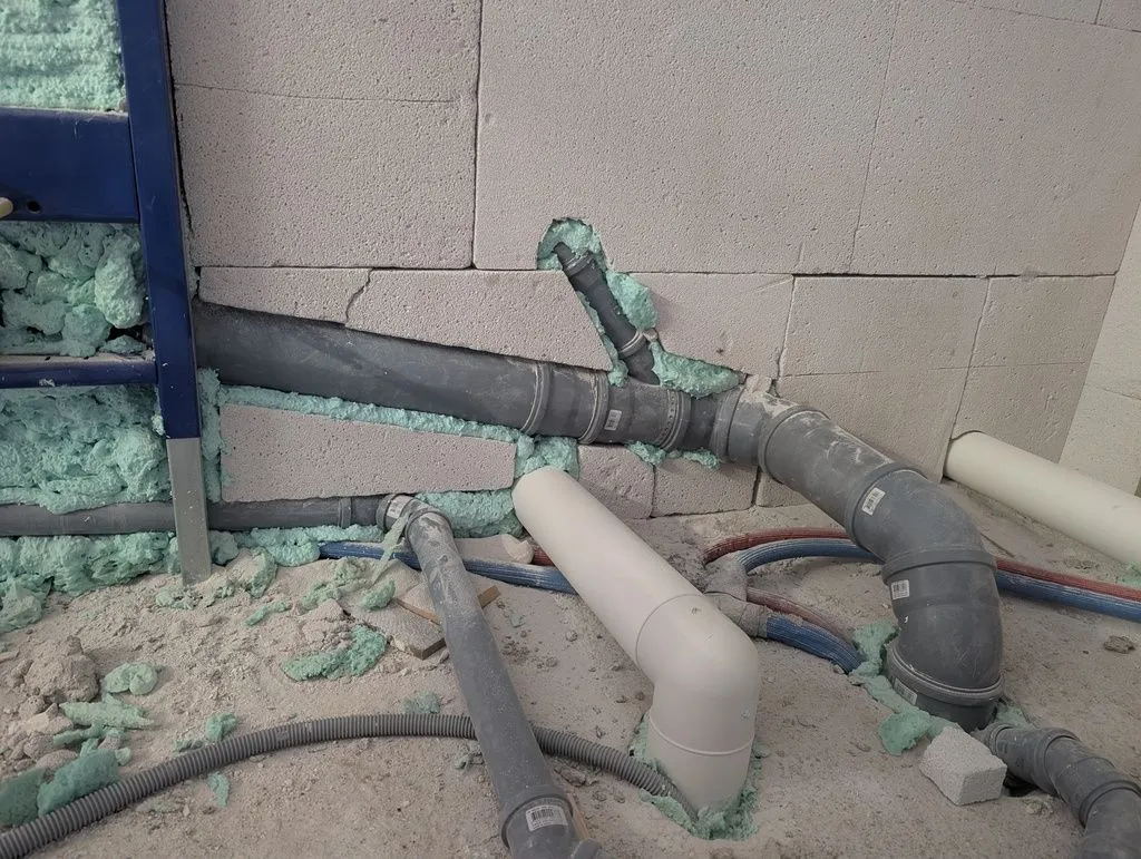
We carved out the Multipor blocks to fit around the plumbing installation—luckily the material is quite soft and easily worked.
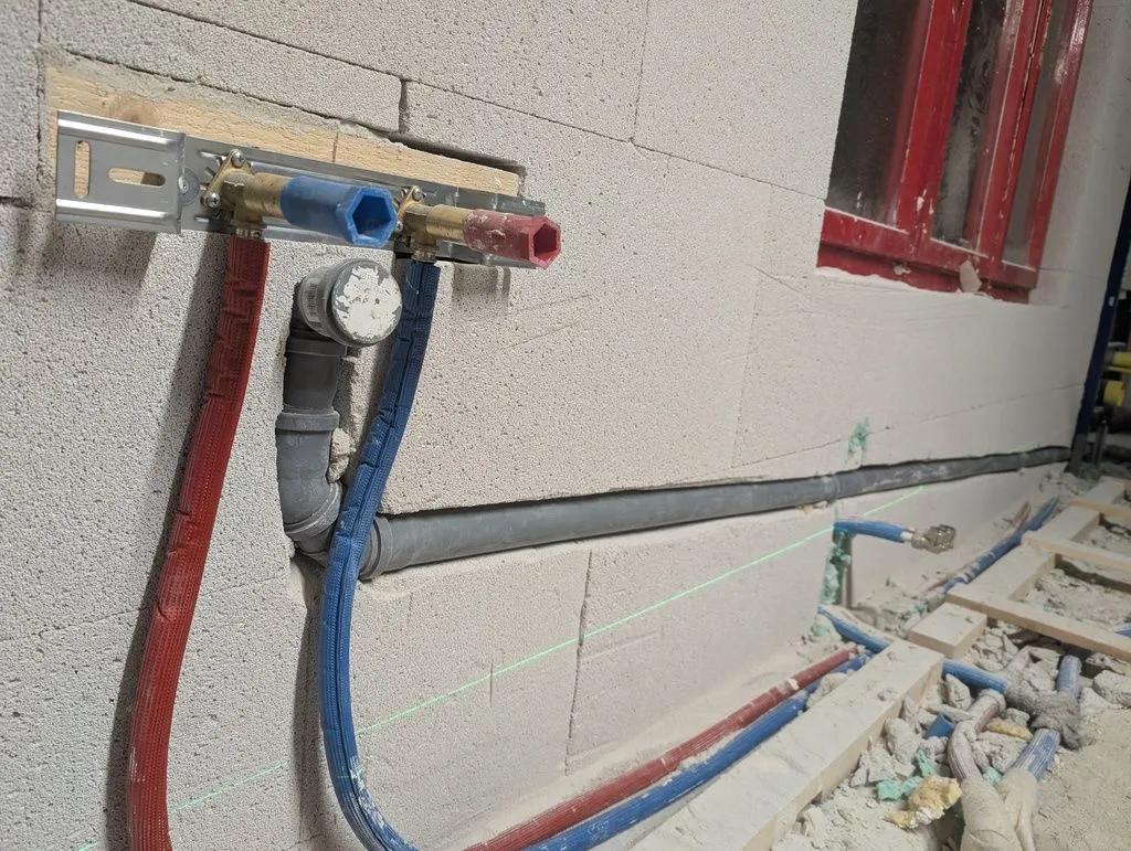
Details around the plumbing installation for the kitchenette.
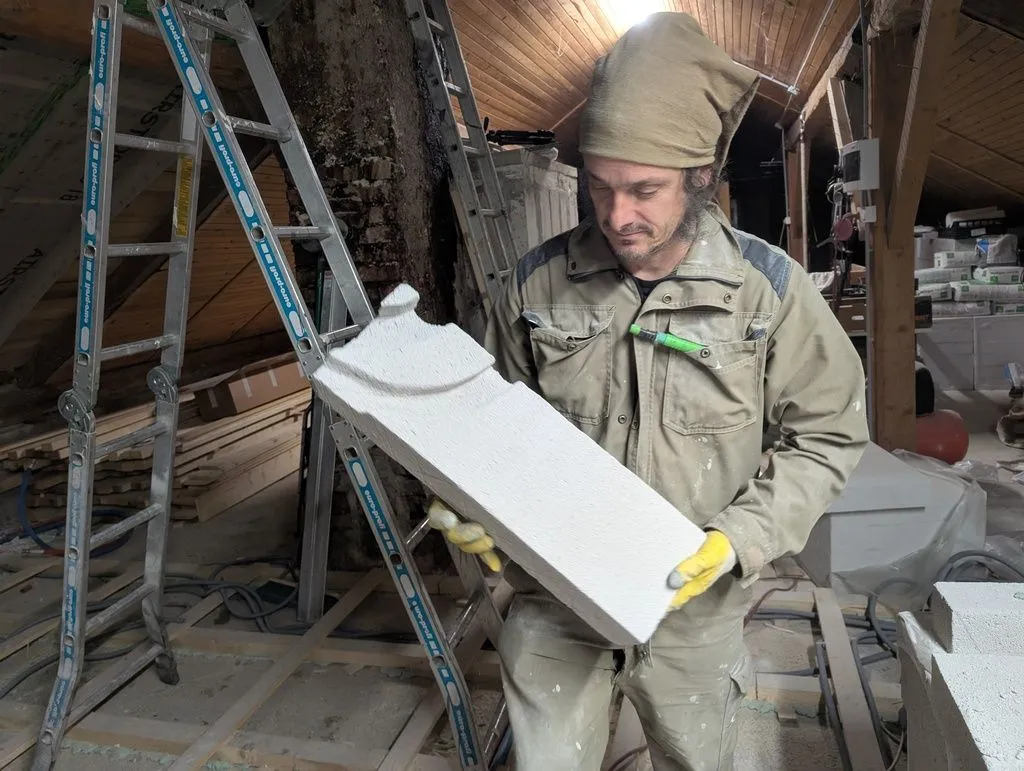
My cousin Anže, who was a crucial help during a few critical phases of the project, including the Multipor installation along the west wall. Here he is holding a block with grooves carved in to fit around water supply lines.
Multipor part 3: concrete blocking for radiators
Multipor is nonstructural and too soft and crumbly to anchor meaningful loads to. So before installing radiators into the Multipor wall, I poured two concrete columns to support the radiator. Overkill perhaps, but they definitely got the job done.
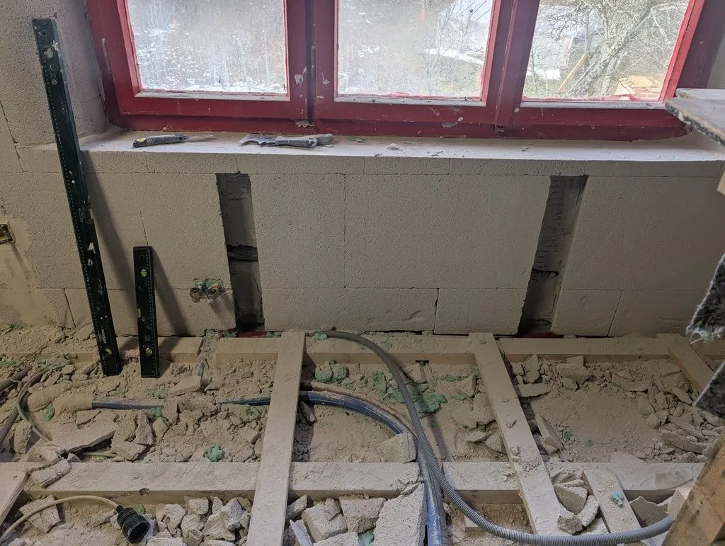
These two vertical channels cut into the Multipor wall will hold concrete columns supporting a radiator (Multipor is nonstructural and can't hold the radiator). The holes are keyed outward for a better mechanical bond between Multipor and concrete.
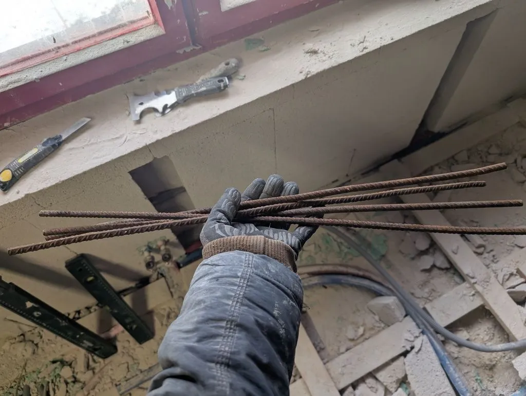
I added rebar stakes into the exterior wall and concrete floor slab as additional structural support, so as to (hopefully) lessen the Multipor's structural role.
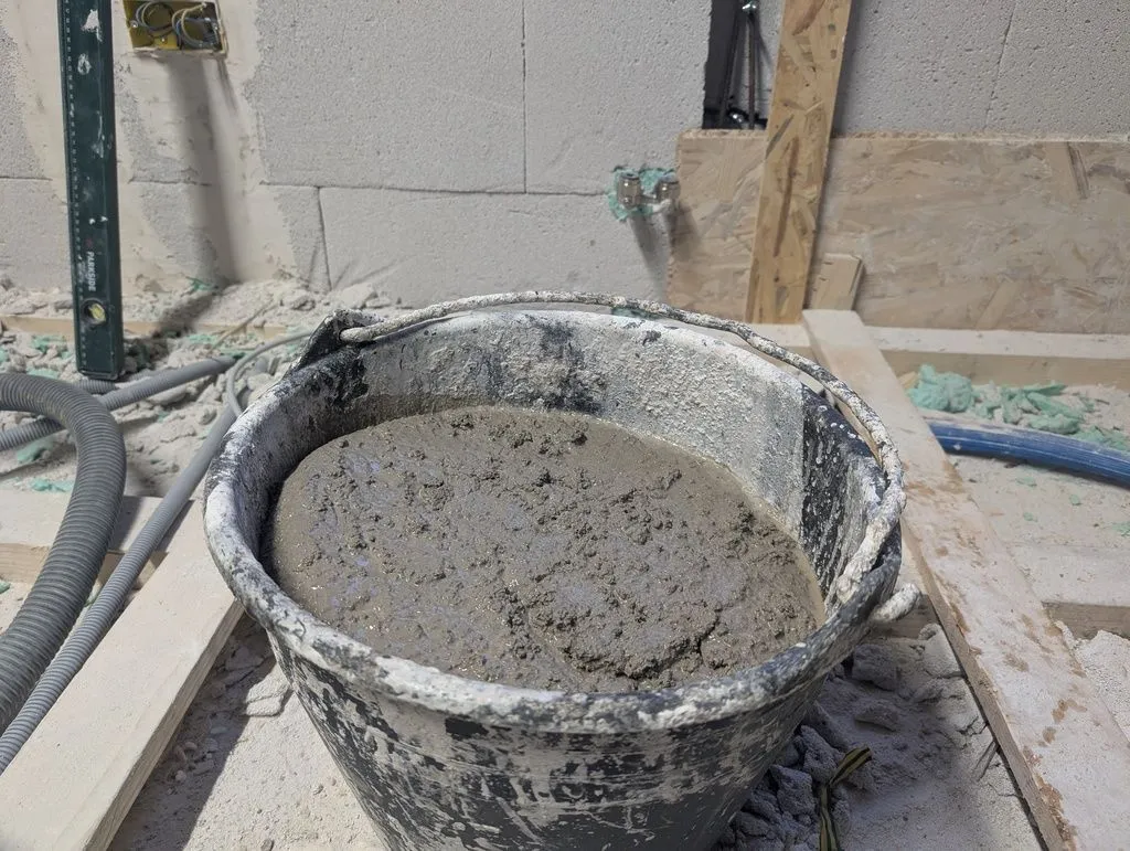
Concrete, ready for pouring.
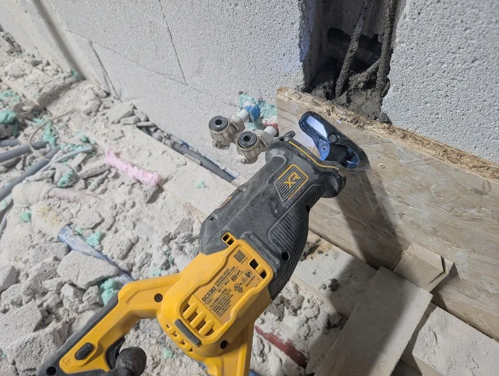
A sawzall with the blade removed makes for a great concrete vibrator.
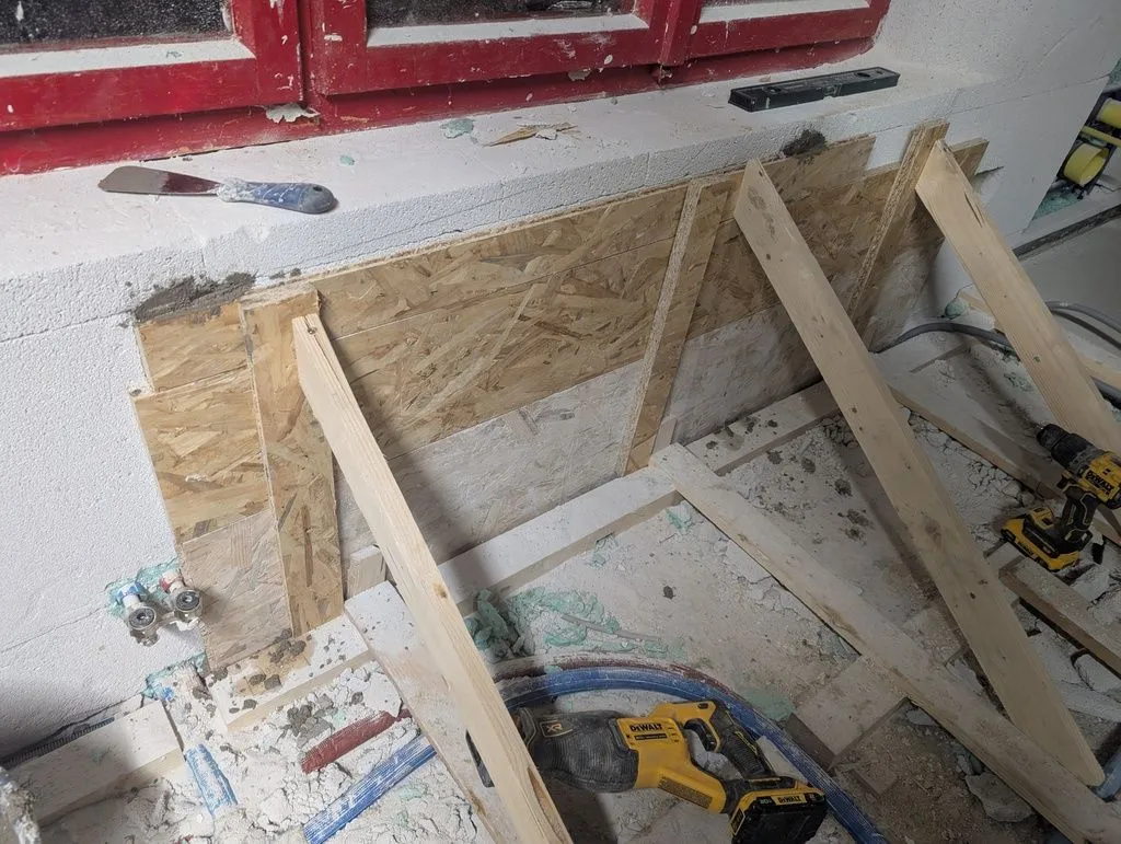
The forms holding the concrete, made of OSB with bracing fastened to the wooden sleepers in the subfloor's substructure.
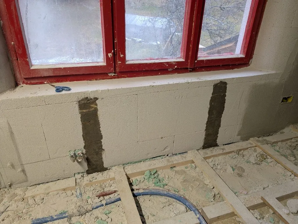
The cured concrete support posts, ready to support a future radiator.
Multipor part 4: finishing the west wall
We finished the west Multipor wall like the north and south walls: a base coat of Multipor adhesive embedded in fiberglass mesh, followed by a finish coat, followed by some touch-up with leveling compound and then paint. For more on Multipor, see part 1, covering the north and south wall installation.
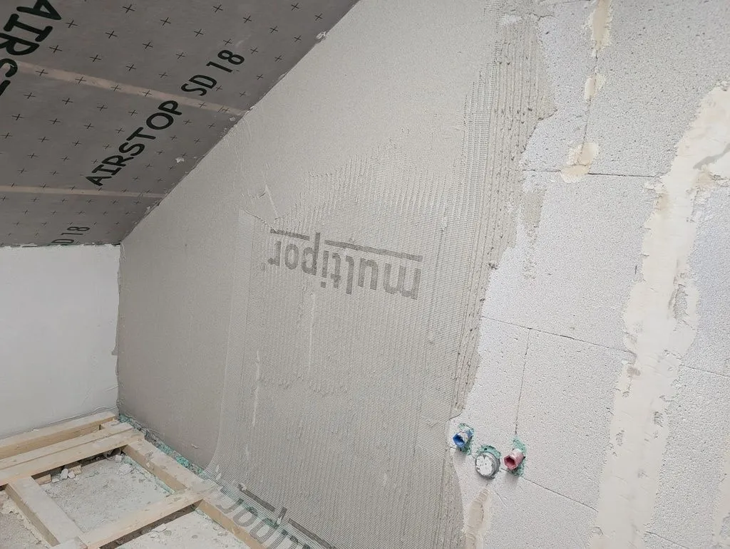
The beginning of the base coat, which is embedded in a fiberglass mesh, like for a classic lime-cement render finish.
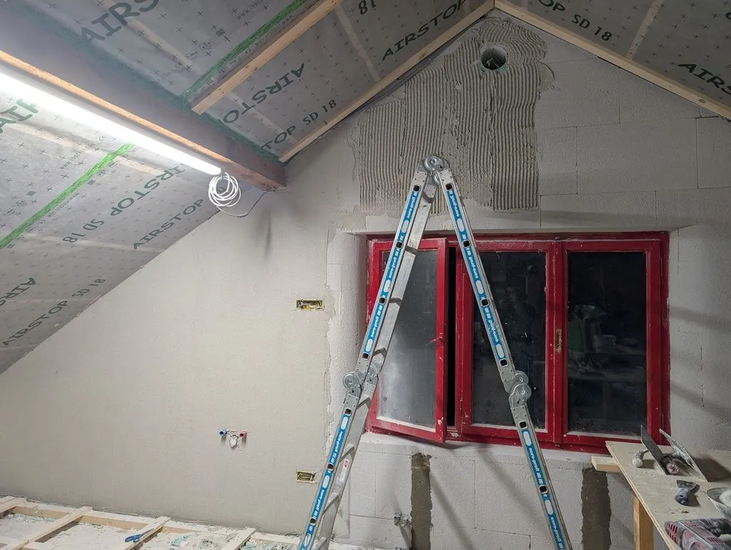
The base coat progressing along the wall
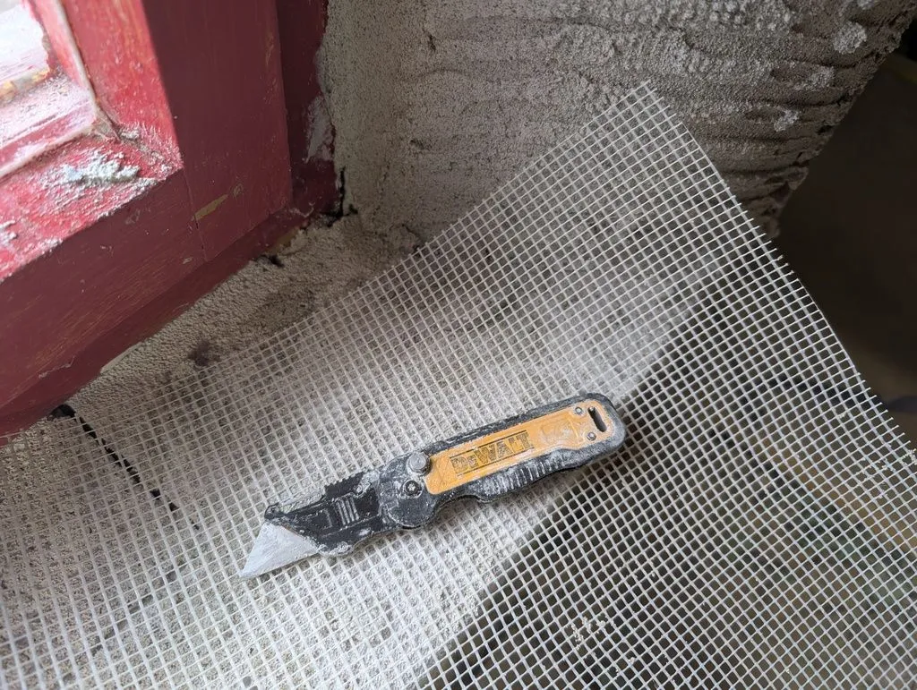
The fiberglass reinforcing mesh embedded in the base coat helps prevent cracking.
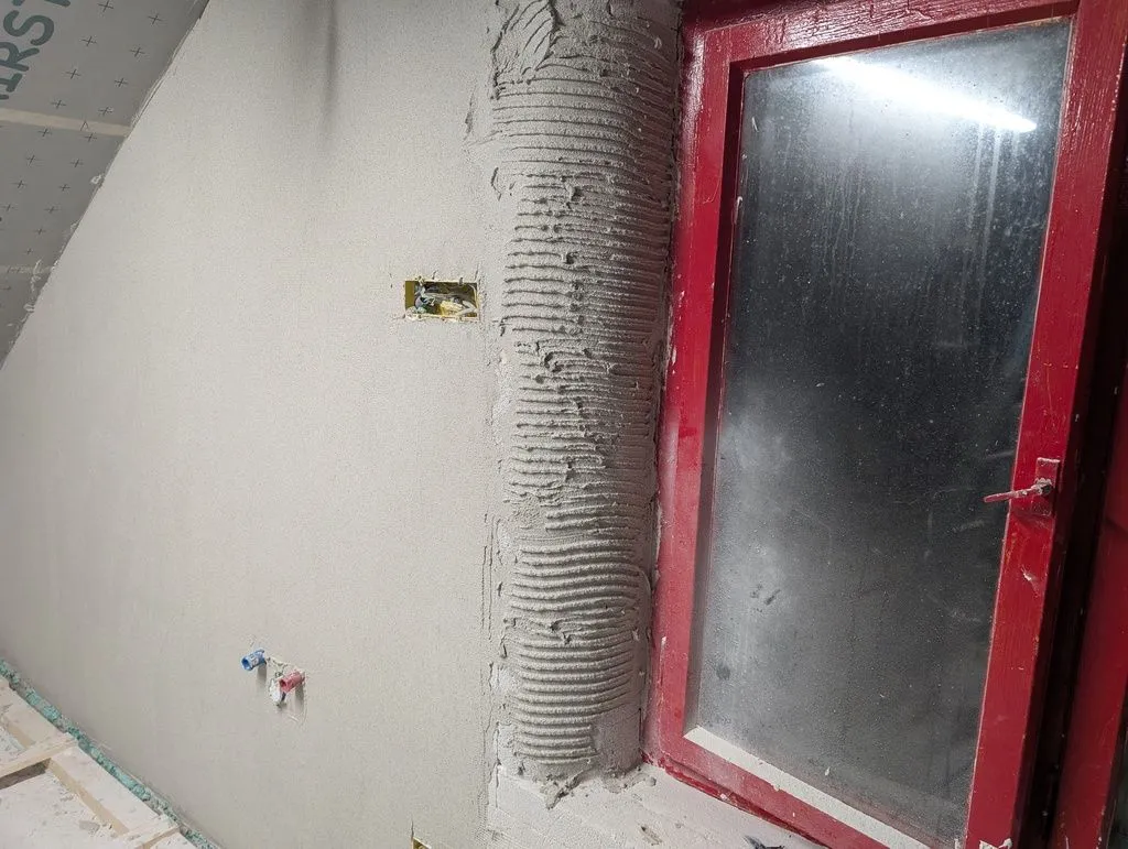
Details around the windows, where the wall is shaped into a rounded reveal.
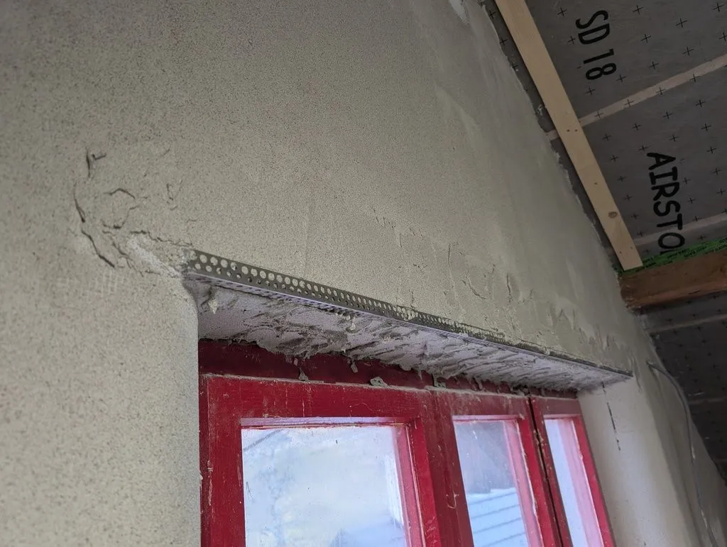
A metal reinforcing bead is placed on along corners, and embedded into the base coat.
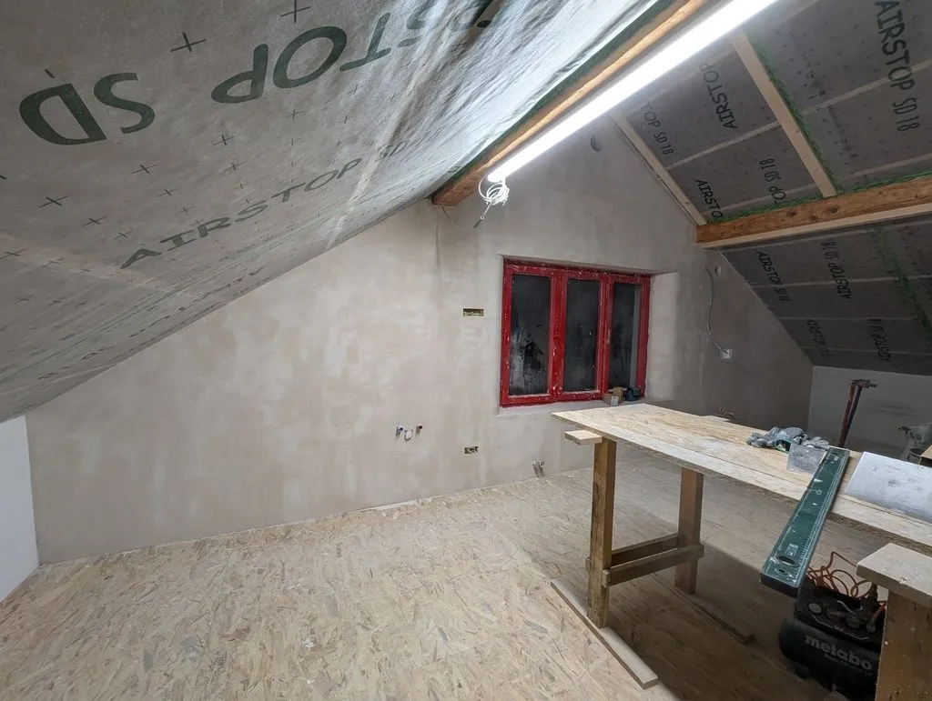
The completed base coat. (Careful readers might notice the OSB subfloor is suddenly installed—I'm jumping around a bit chronologically for logical consistency, and will cover the subfloor installation in a later section.)
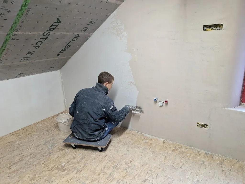
Trowelling on the finish coat—the transport dolly makes for a convenient mobile chair.
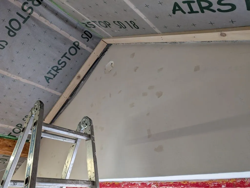
Patching a few low spots I missed during the finish coat—the patches are fresh and visible, but will dry to the same color as the rest of the finish.
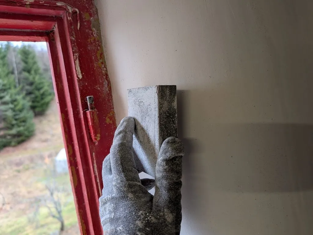
Sanding down rough spots with a drywall sanding block.
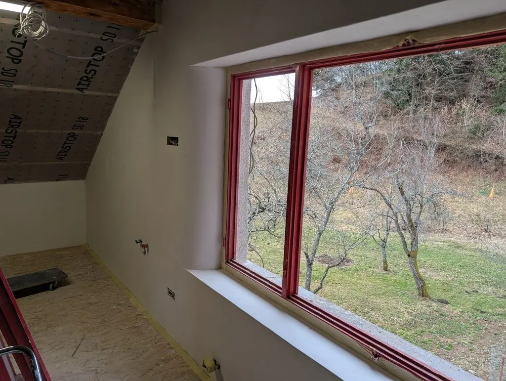
The completed finish coat.
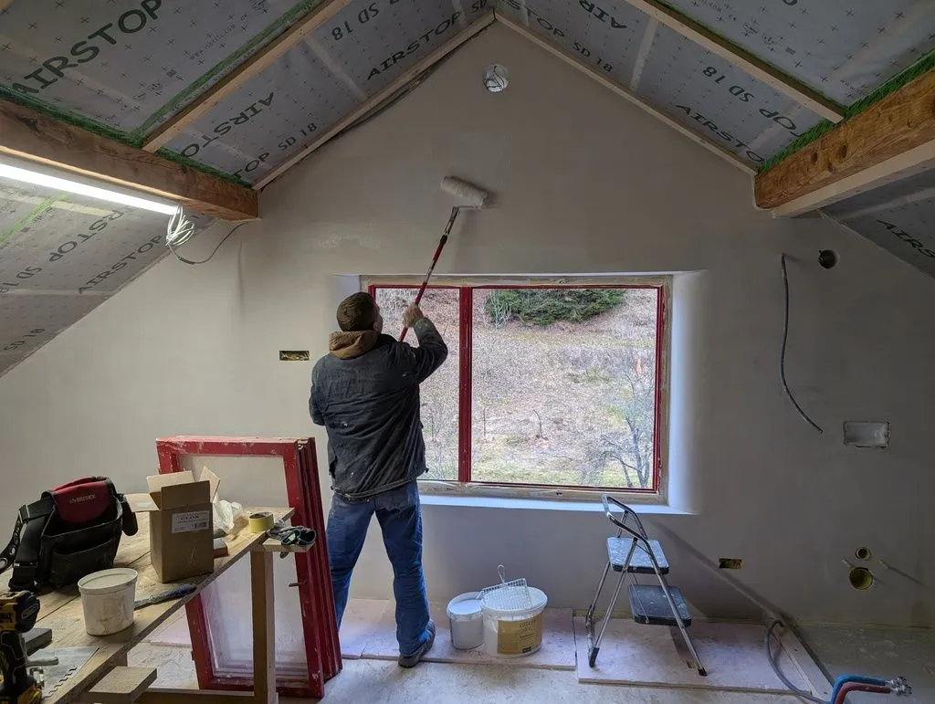
Painting the wall—the roller and extension pole come in handy for the high areas.
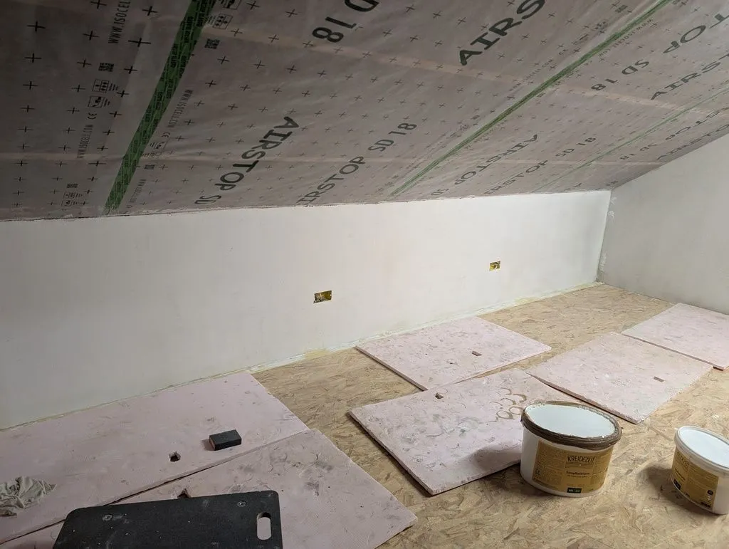
We painted the north and south walls together with the west wall.
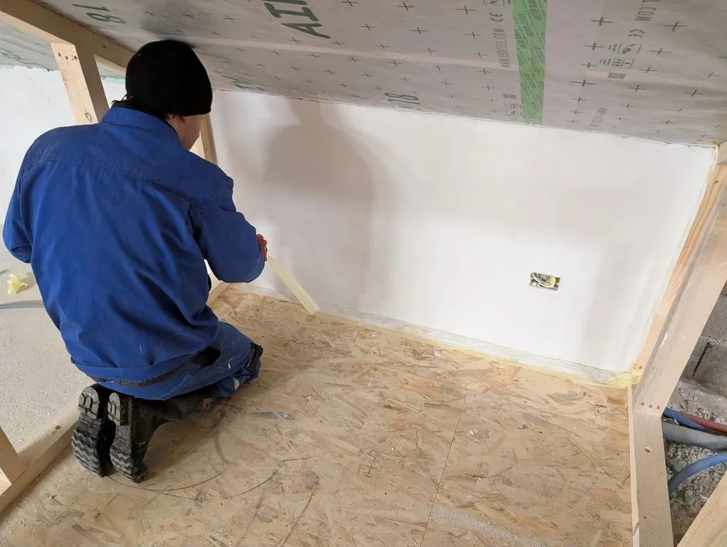
All done! Martin, who helped throughout the painting process, is removing masking tape after we finished painting.
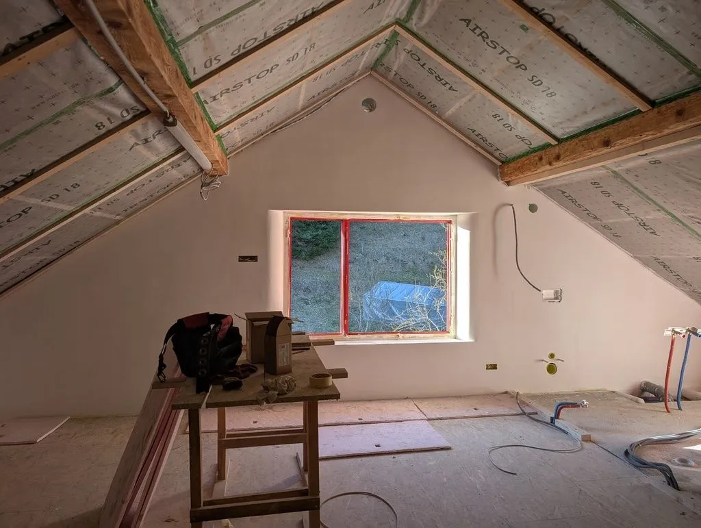
The painted west wall.
Interlude: cleaning up the subfloor substructure
We built the subfloor substructure far earlier than necessary. Result: tons of construction waste accumulating around and under the substructure, which needed to be cleaned up before installing the subfloor.
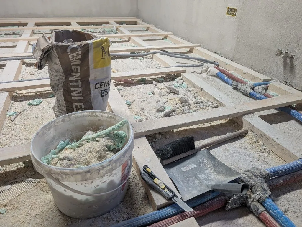
Lost of construction waste accumulated under and around the subfloor substructure.
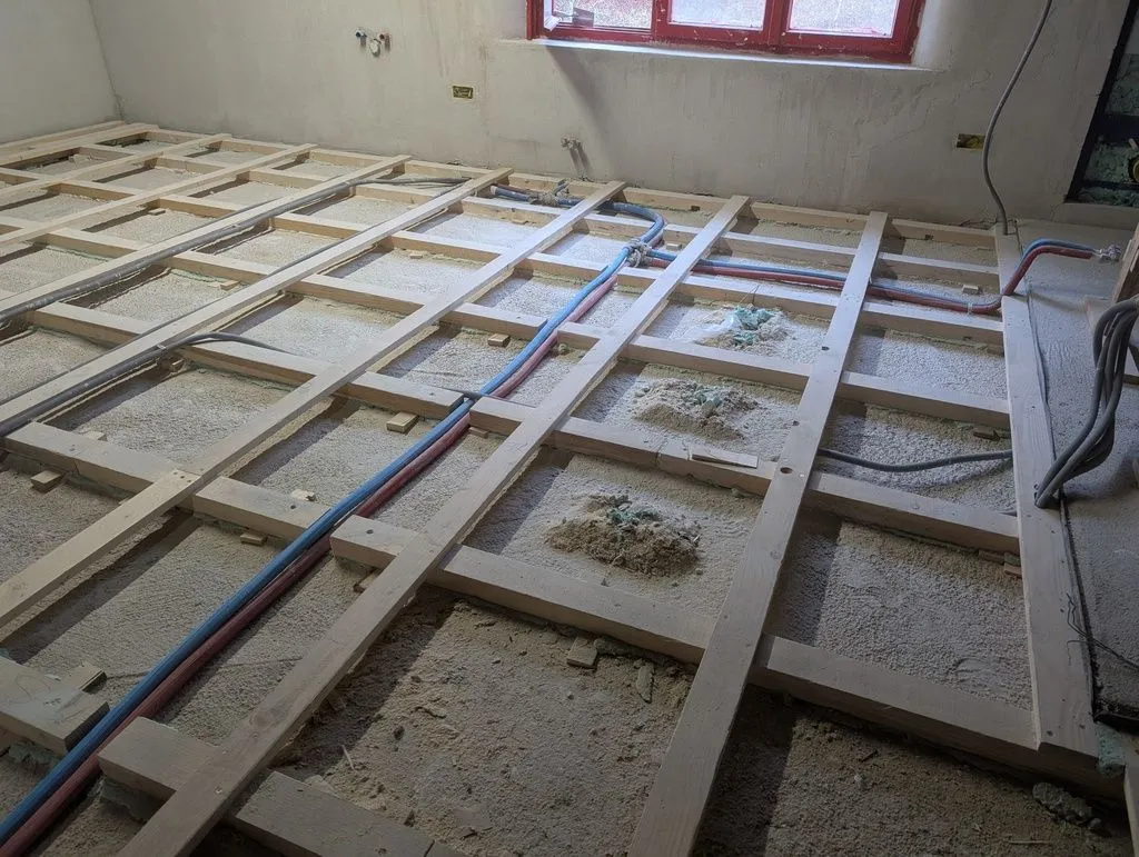
We first collected the waste in rough piles, which we removed with a dust pan...
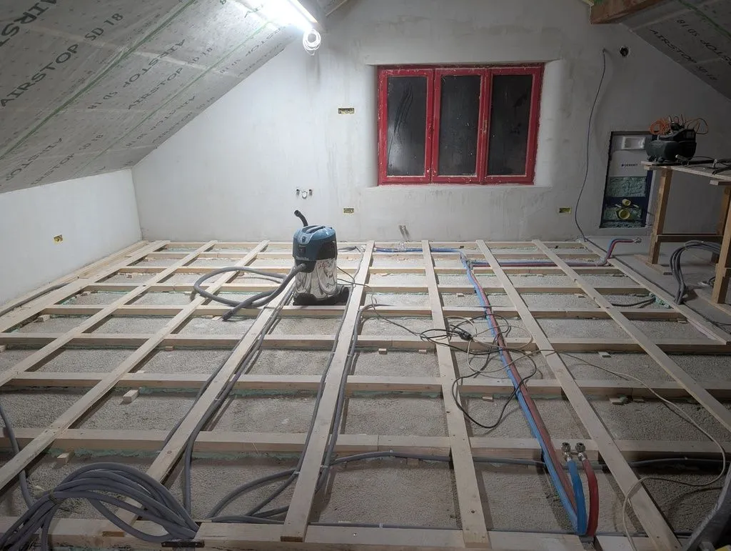
...followed by a second pass with a shop vac.
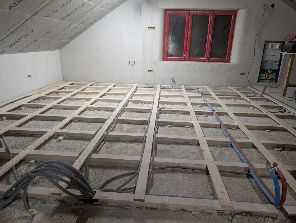
Done! The cleaned-out subfloor, ready for insulation and the subfloor.
Insulating the subfloor
We insulated the subfloor with scraps of mineral wool we had lying around from insulating the ceiling and previous work on the property. This step was not particularly necessary from a building physics perspective because the living space below is heated—but it was a great way to dispose of all of the scraps we had lying around in an at least marginally useful manner, rather than hauling them to the dump.
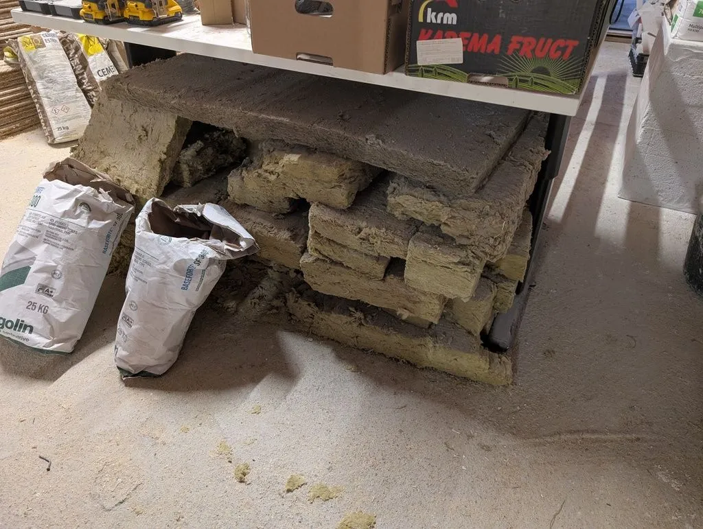
The mineral wool scraps we would use to insulate the subfloor. This is a mixture of glass and rock wool from insulating the ceiling and previous work on the property.
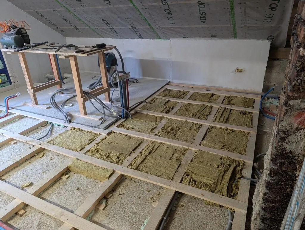
The first pieces of glass wool packed into the subfloor substructure.
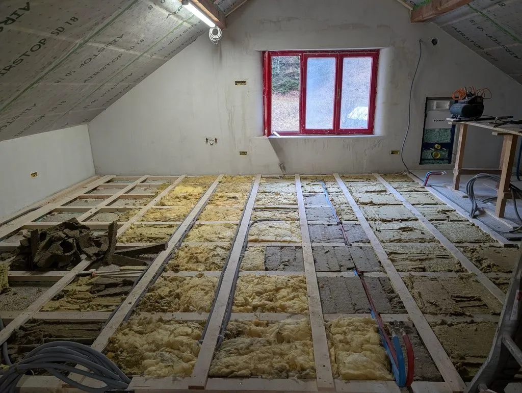
The subfloor insulation 80% complete.
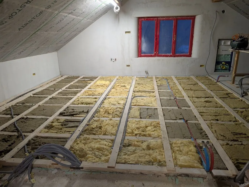
All done! The completed subfloor insulation.
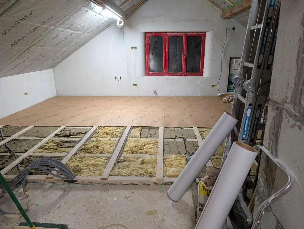
We added a layer of heavy-duty construction paper over the insulation to contain the glass wool, and as an underlayment for the subfloor.
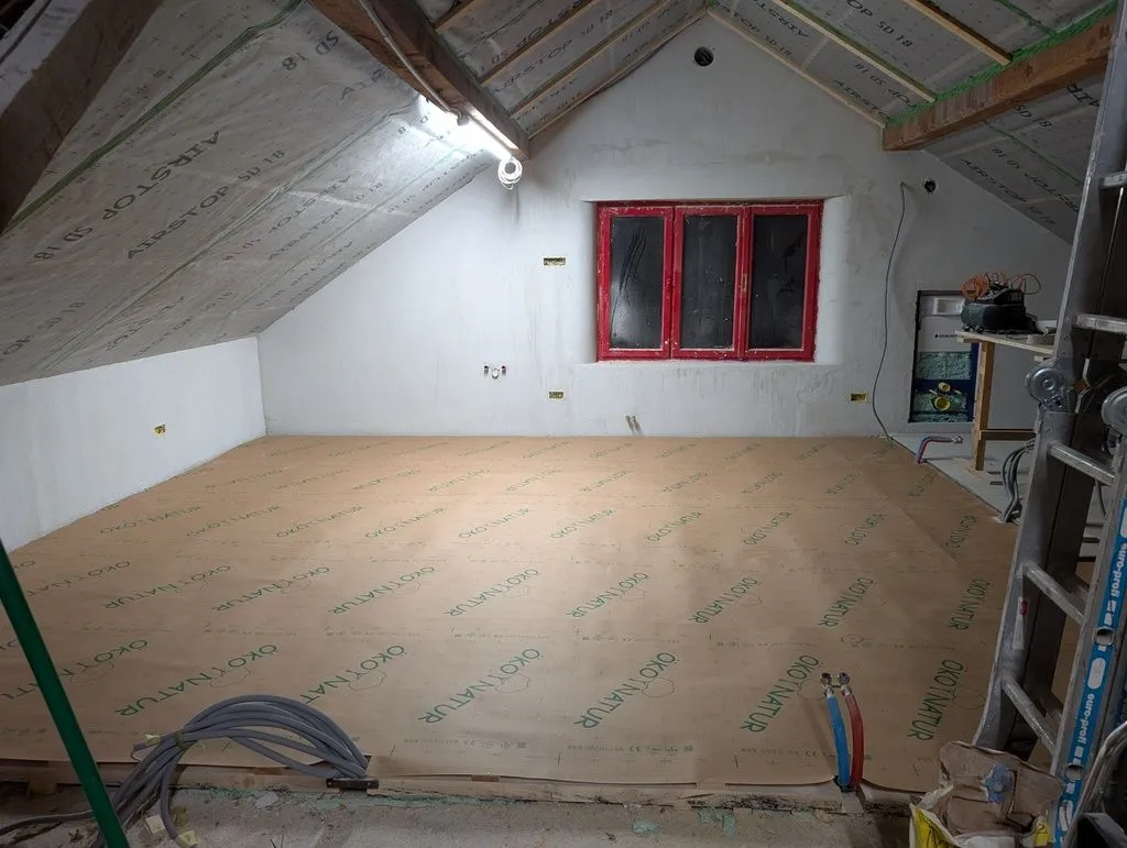
The insulated subfloor covered with construction paper, ready for the OSB subfloor.
Installing the OSB subfloor
We used a single layer of 22 mm (a bit under 1 inch) tongue and groove OSB for the subfloor. The sleepers in the subfloor substructure an spaced to match the factor dimensions of the OSB boards.
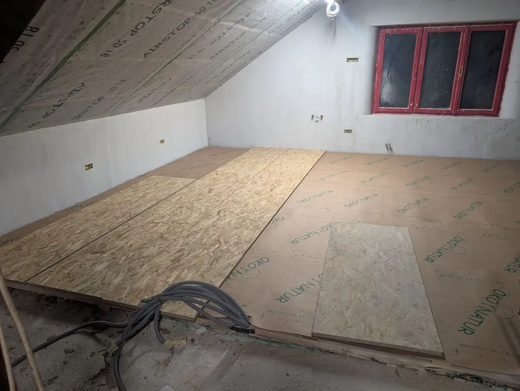
Test-fitting the first few subfloor boards.
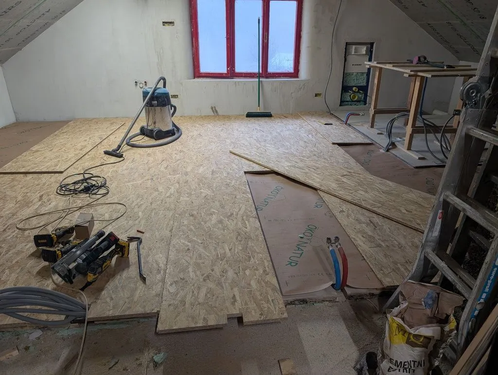
The installation of the OSB subfloor in progress.
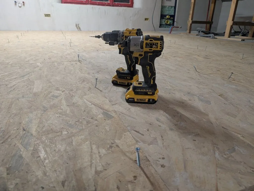
We fastened the subfloor to the substructure with screws. (Nails fired from a pneumatic nailgun are more conventional and faster, but I didn't own a framing nailgun at the time of this job. I did own an 18 gauge brad nailer, which will feature prominently when we get to finish work, but a brad nailer is not strong enough to attach the subfloor—you'd want a 15 or 16 gauge framing nailer.)
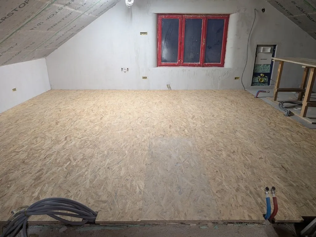
The completed OSB subfloor.
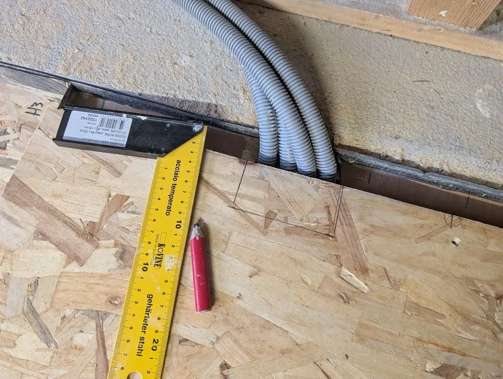
Detail showing the process of notching the subfloor to fit around electrical conduit coming up out of the floor.
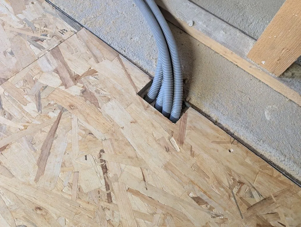
The notched board fitting nicely around the conduit.
Installing radiators (subcontracted)
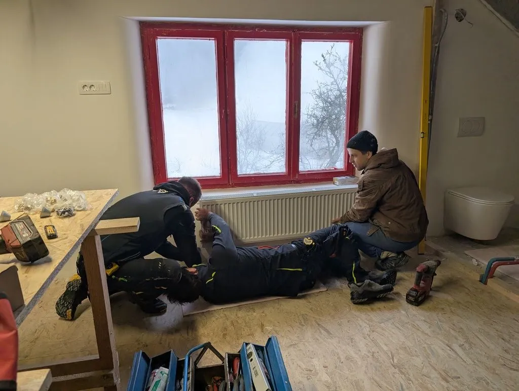
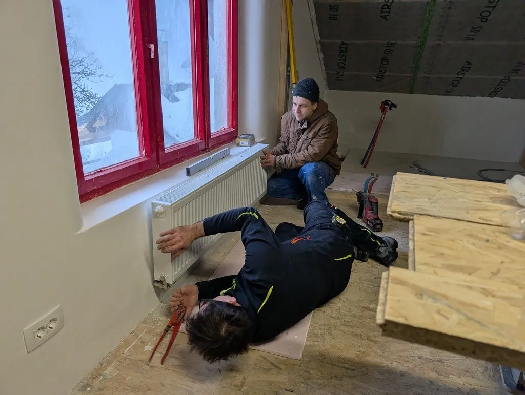
As mentioned in an earlier section, we subcontracted the plumbing and heating work. The living space is heated with two radiators—one on each side of the space—supplied by a central heating system.
Framing
The partition wall (between the finished living space and the rest of the unfinished attic) is framed using standard stud framing techniques, with three nuances:
- We used 50 mm x 80 mm studs—the closest commonly available dimension in Slovenia to the USA's ubiquitous 2 x 4.
- The studs are placed 625 mm on center (about 24 inches) to match the standard width of sheet goods in the EU.
- We built the walls in place (rather than building on the floor and tilting them up into place, as is common in commercial platform frame construction) for two reasons: (1) building in place made it easer to match the slopped roof; and (2) I'm a one-man crew and would struggle to lift a full wall into place.
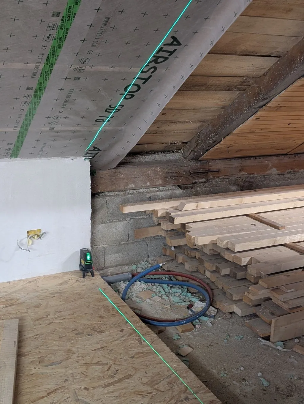
Using a laser level to lay out the position of the top and bottom plates.
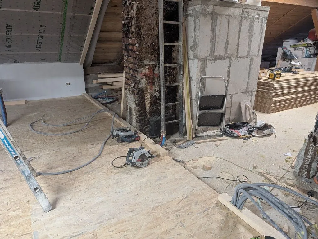
Installing the top and bottom plates (the bottom plate is notched to allow conduit to come up into the wall).
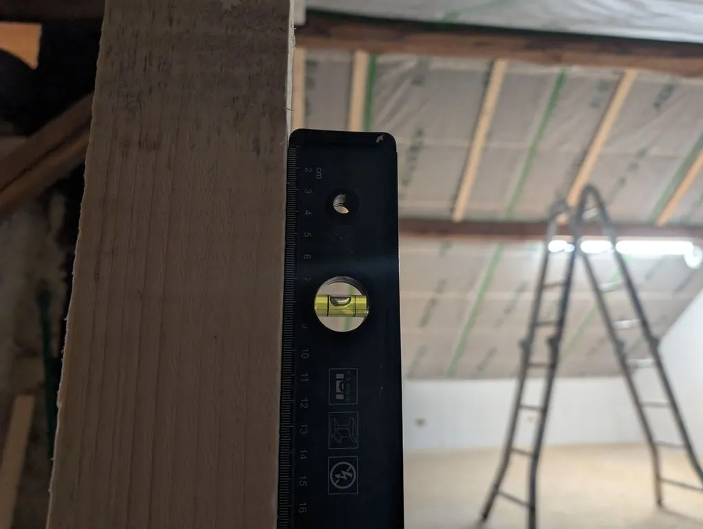
Verifying the studs are level.
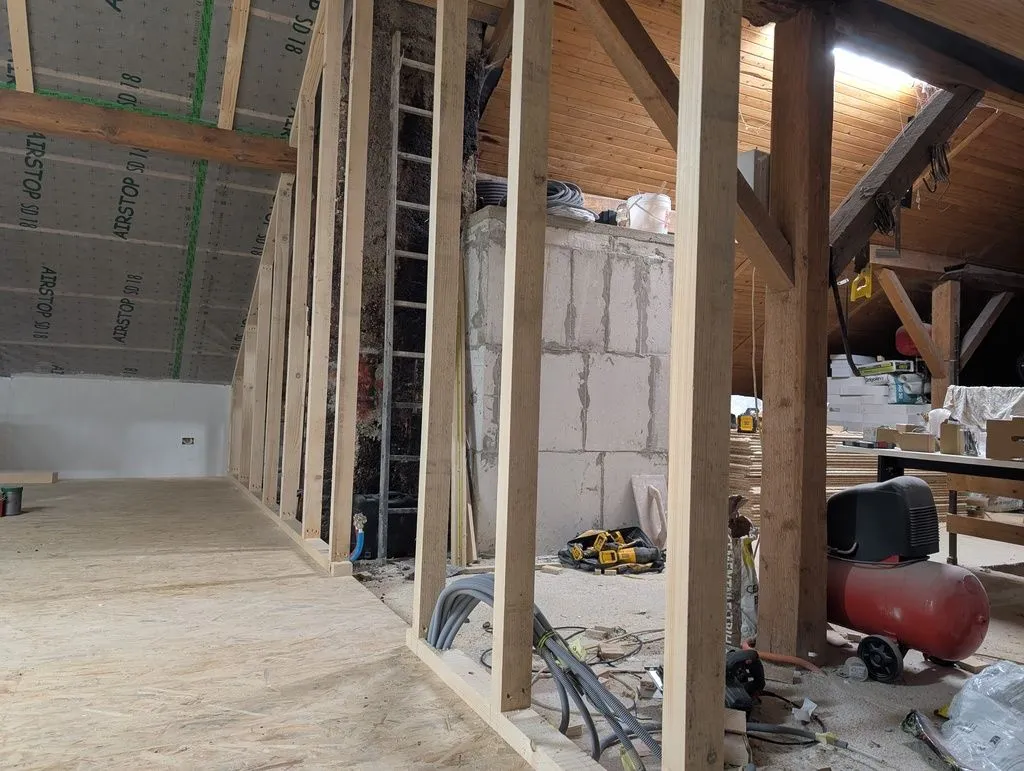
The studs installed.
Interlude: refinishing timber beams
The roof is built with heavy timber framing, and we chose to leave the heavy timber beams exposed as an intentional design detail. We made the beams presentable by first sanding down the rough-sawn surface with a flap disk attached to an angle grinder, then finishing the beams with linseed oil.
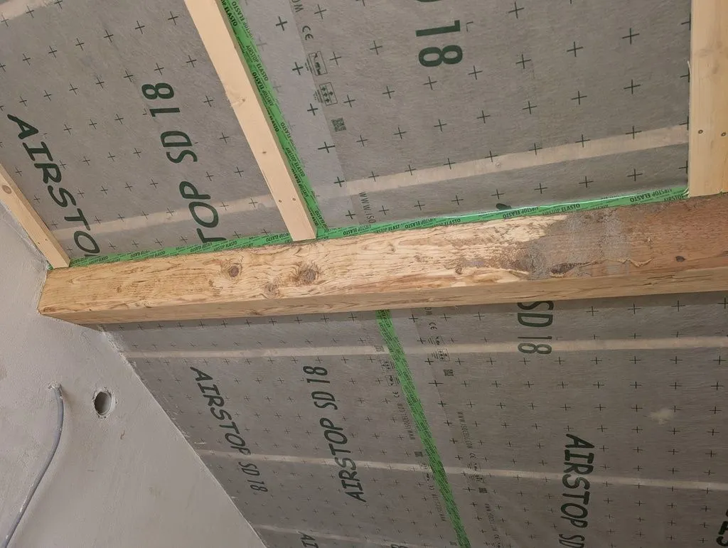
Sanding the beams in progress—the sanded surface is on the left, and the original rough-sawn surface on the right.
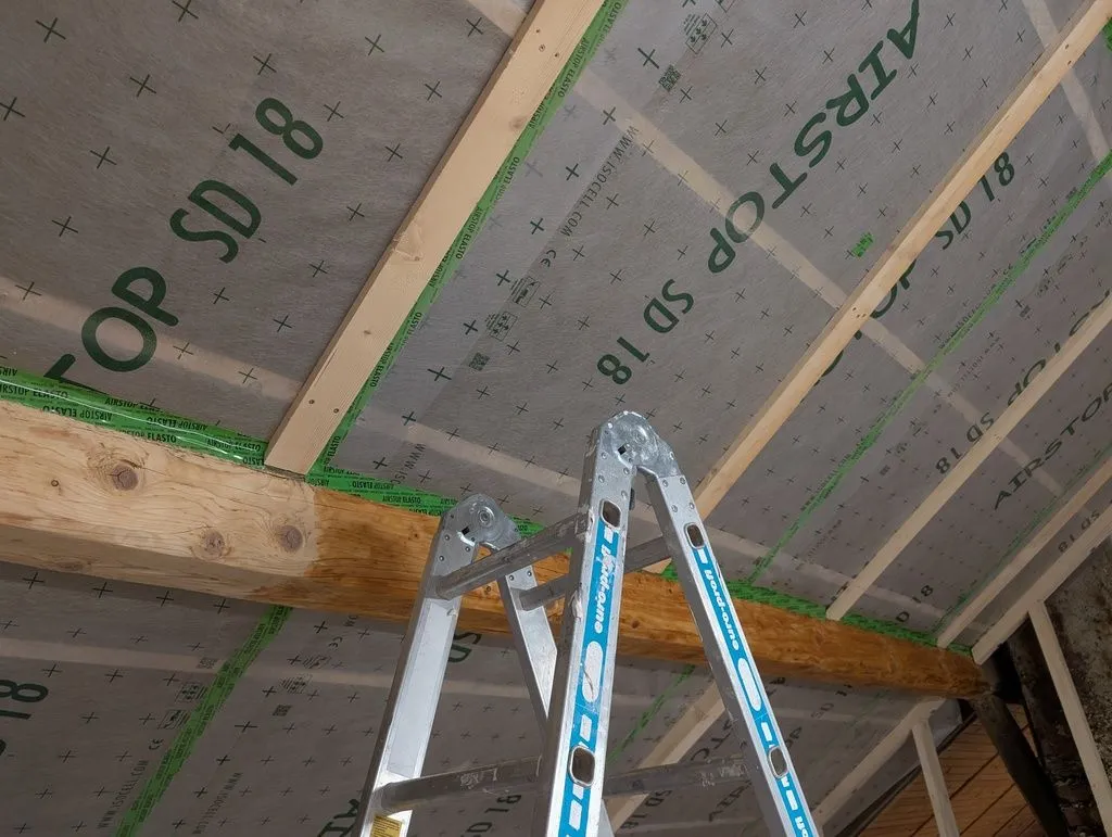
Most of the sanding was done on a ladder, so as to reach the beams.
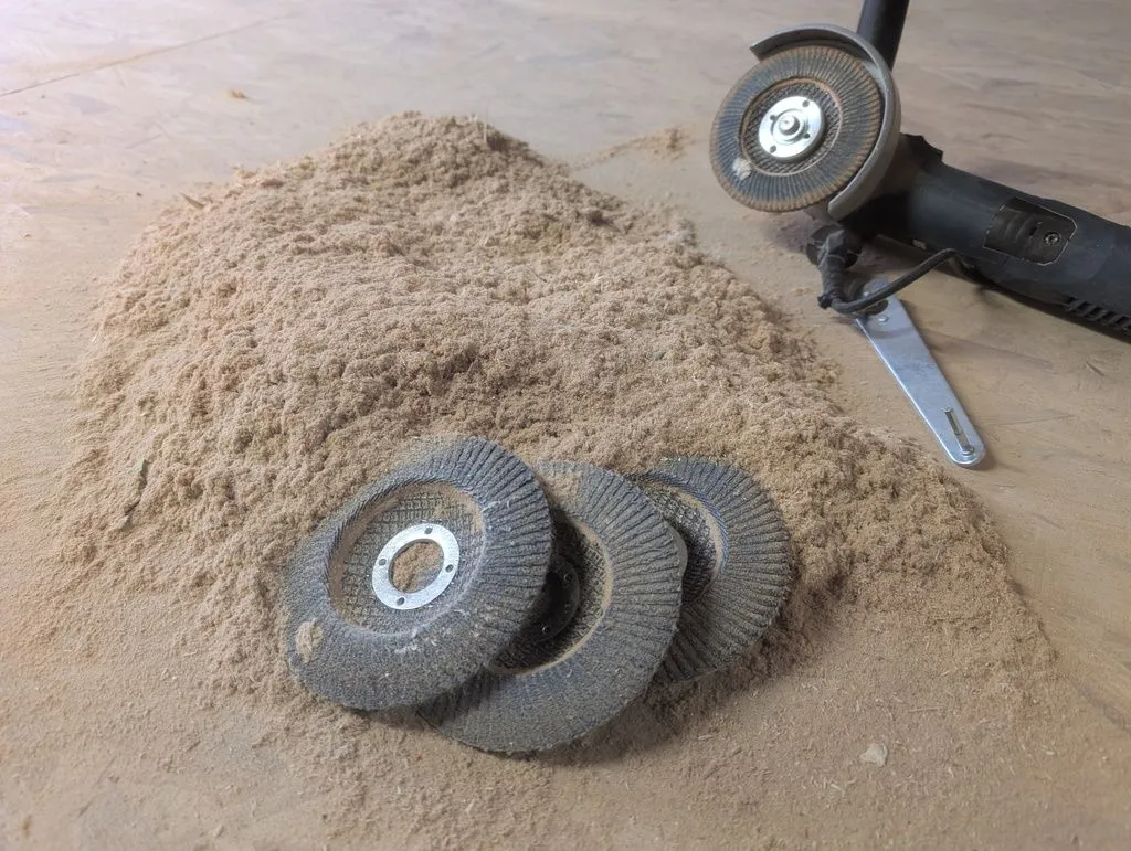
We addressed this relatively heavy-duty job using an angle grinder and flap disks, which are far more aggressive than a orbital sander. You can see all the flap disks we burned through on the job.
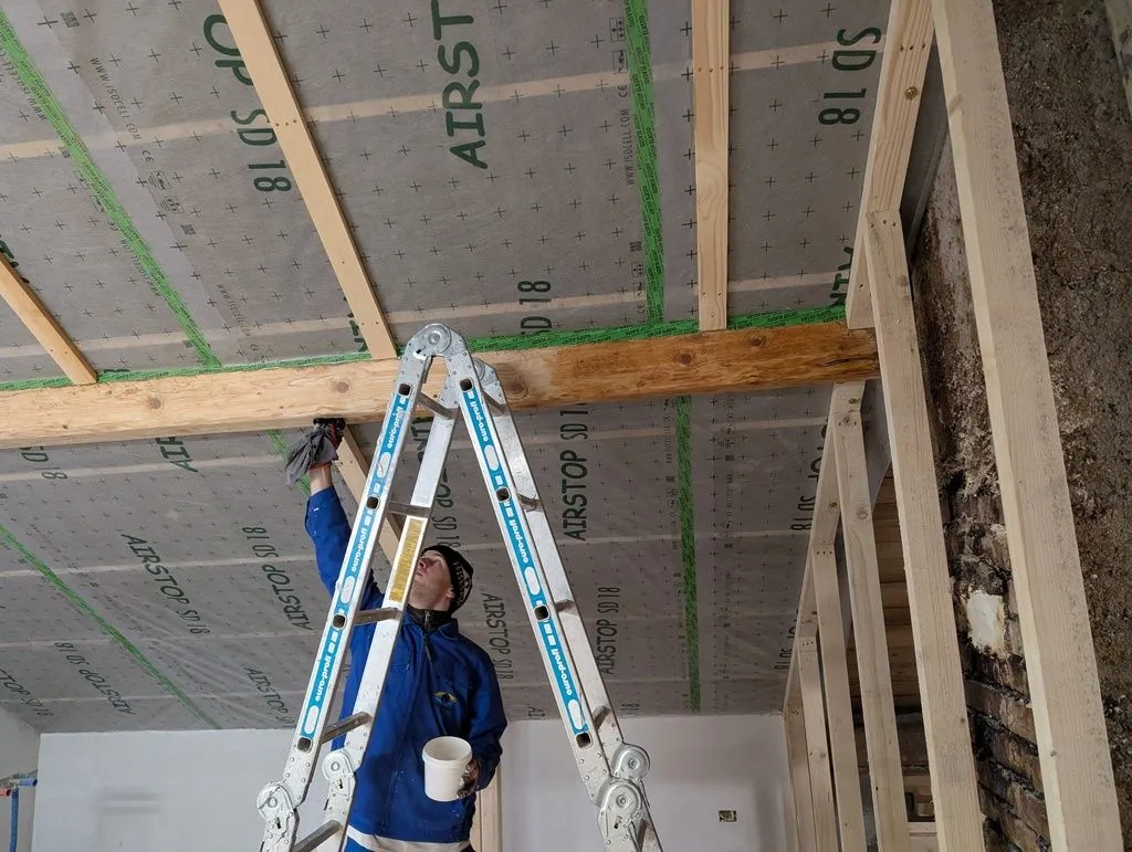
Here is Martin finishing the beams with linseed oil—he took care of almost all oil-based finishing on the job-both the beams and the later tongue and groove wall finish.
Sheathing interior walls
We sheathed interior walls on one side with 12.5 mm tongue-and-groove OSB. This helps tie the wall together structurally, even if it is not a load-bearing wall, is a convenient nailing and mounting surface, and makes it easier to install electrical outlets.
We fastened the sheathing to the studs with screws (nails fired from a pneumatic nailgun are more conventional and faster, but I didn't own a framing nailgun at the time of this job).
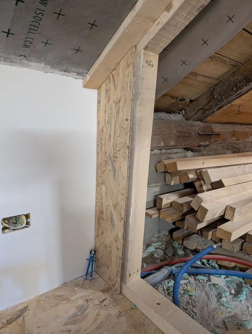
The first piece of sheathing going up on the main partition wall.
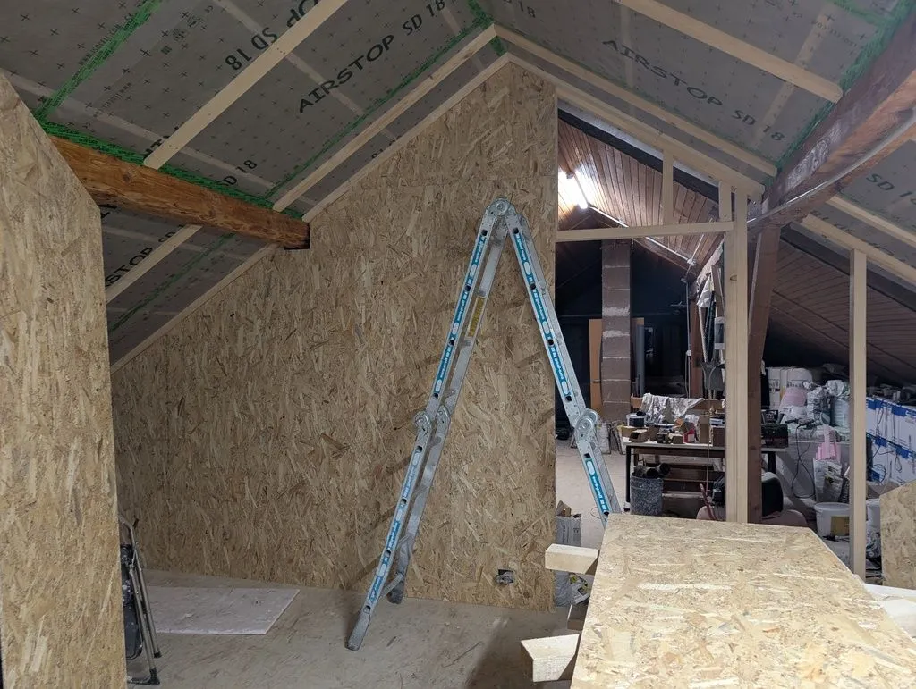
Sheathing of the main partition wall halfway complete.
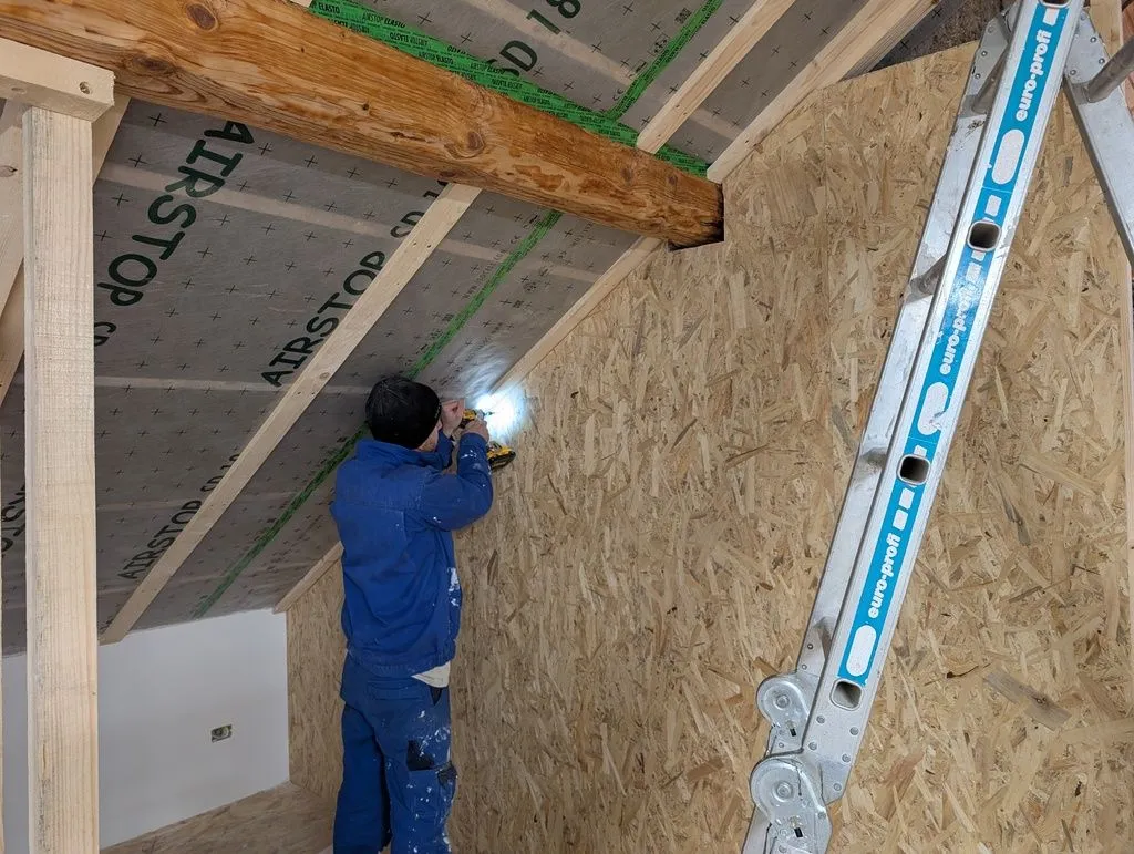
Martin fastening the OSB to the studs—we worked together on the sheathing—I did the cutting and he did the fastening.
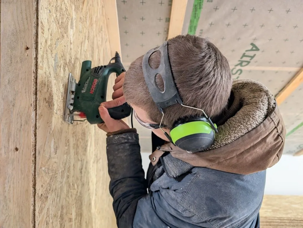
Using a jigsaw to cut a hole for electrical outlets.
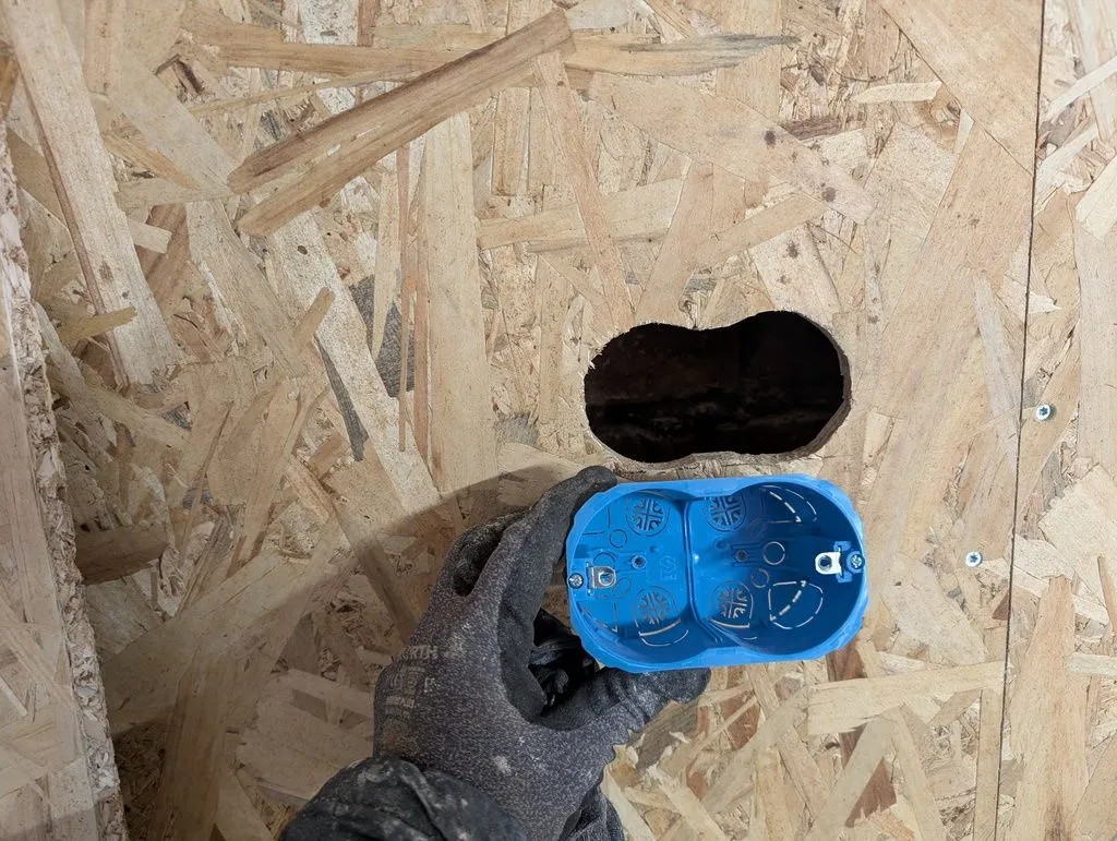
A hole cut in the OSB sheathing for an electrical box that will hold outlets and switches.
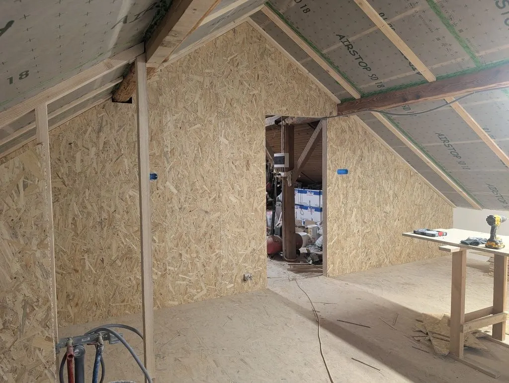
The completed sheathing of the main partition wall.
Insulating the main partition wall
We insulated the main partition wall between the finished living space and the rest of the unfinished attic with glass wool placed between the wall studs.
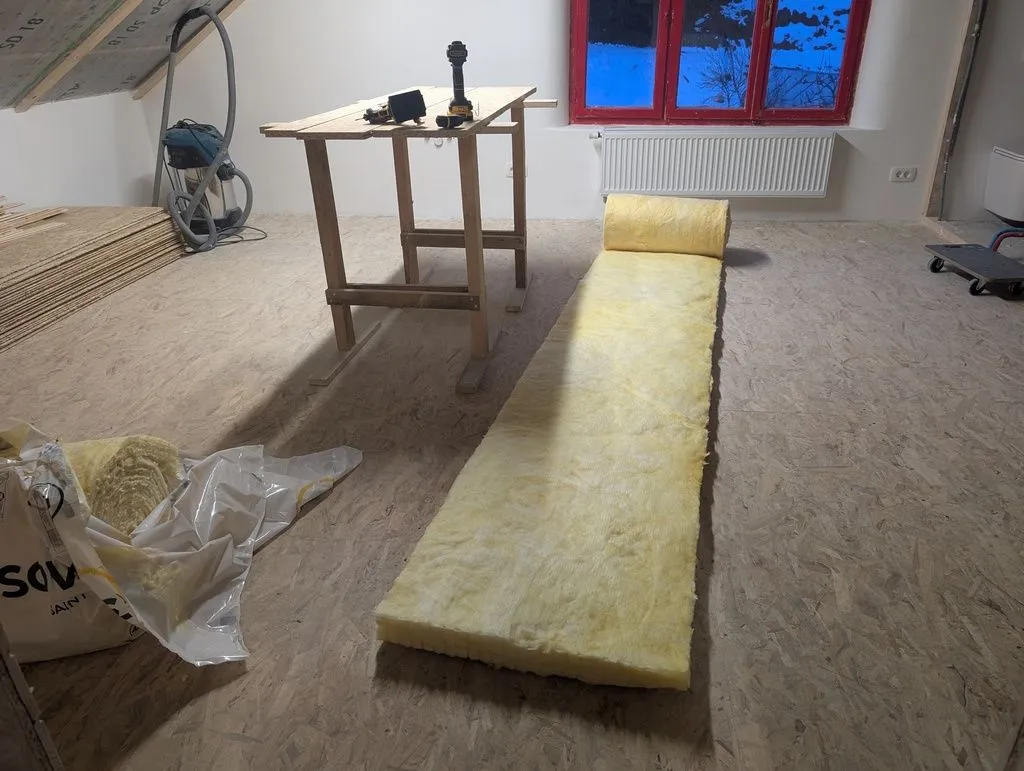
A batt of glass wool, rolled out and ready for installation.
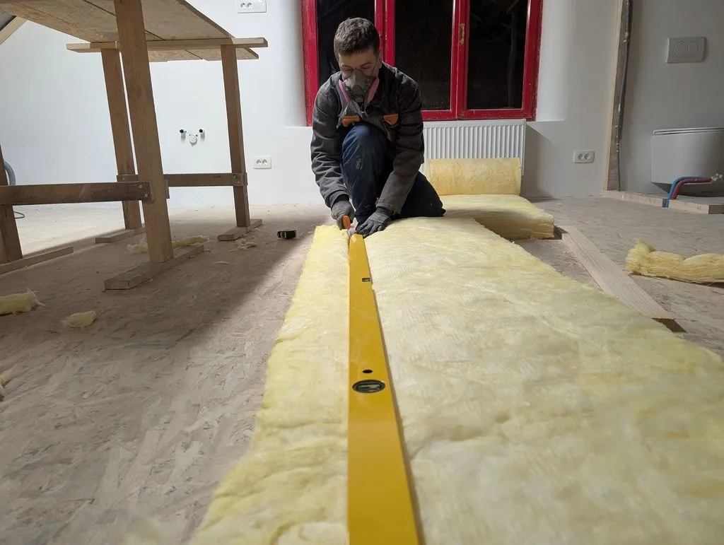
Using a straightedge to cut the glass wool to width.
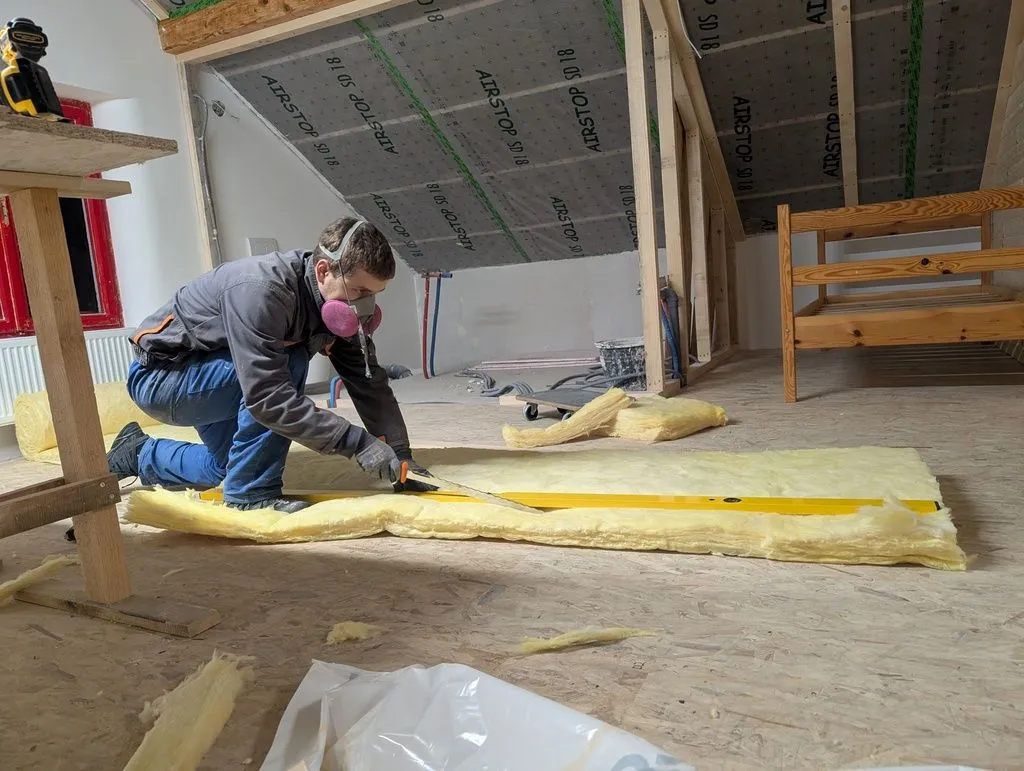
Ditto.
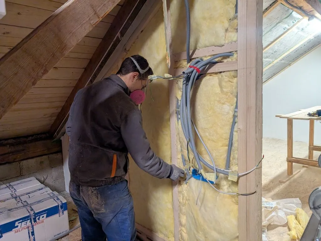
Installing insulation around the conduit near the future electrical panel.
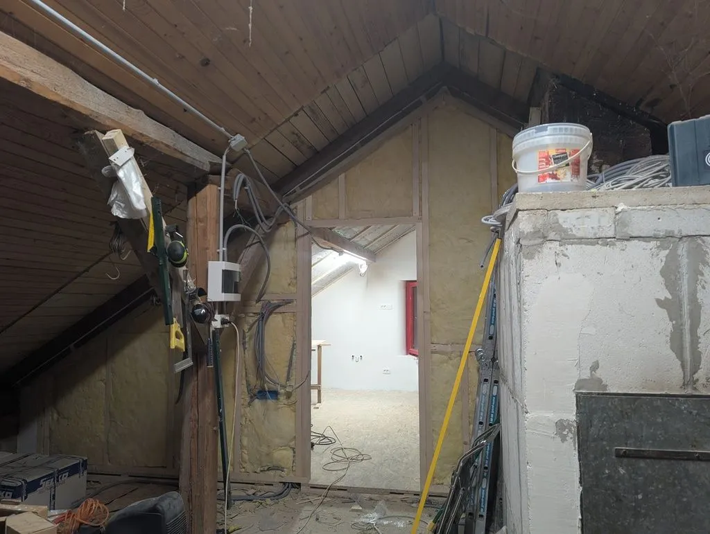
All done! The insulation installed in the main partition wall, which is now ready for the tongue and groove wall finish, installed next.
Tounge and groove wall finish
We finished the interior walls with 12 mm spruce tongue and grove boards. We're lucky to have a supplier just a few kilometers from us! The boards were installed with 18 gauge brad nails fired from a pneumatic brad nailer and finished with linseed oil.
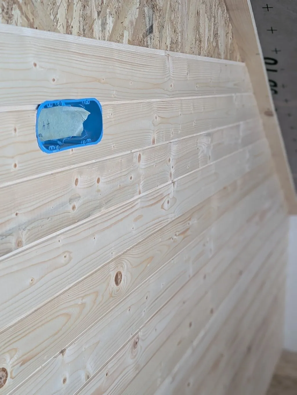
The first boards going up on the main partition wall. The natural wood grain makes for a warm, cozy interior.
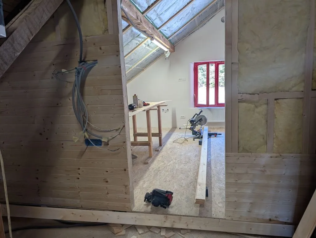
We used the same tongue and groove sheathing for the exterior of the main partition wall.
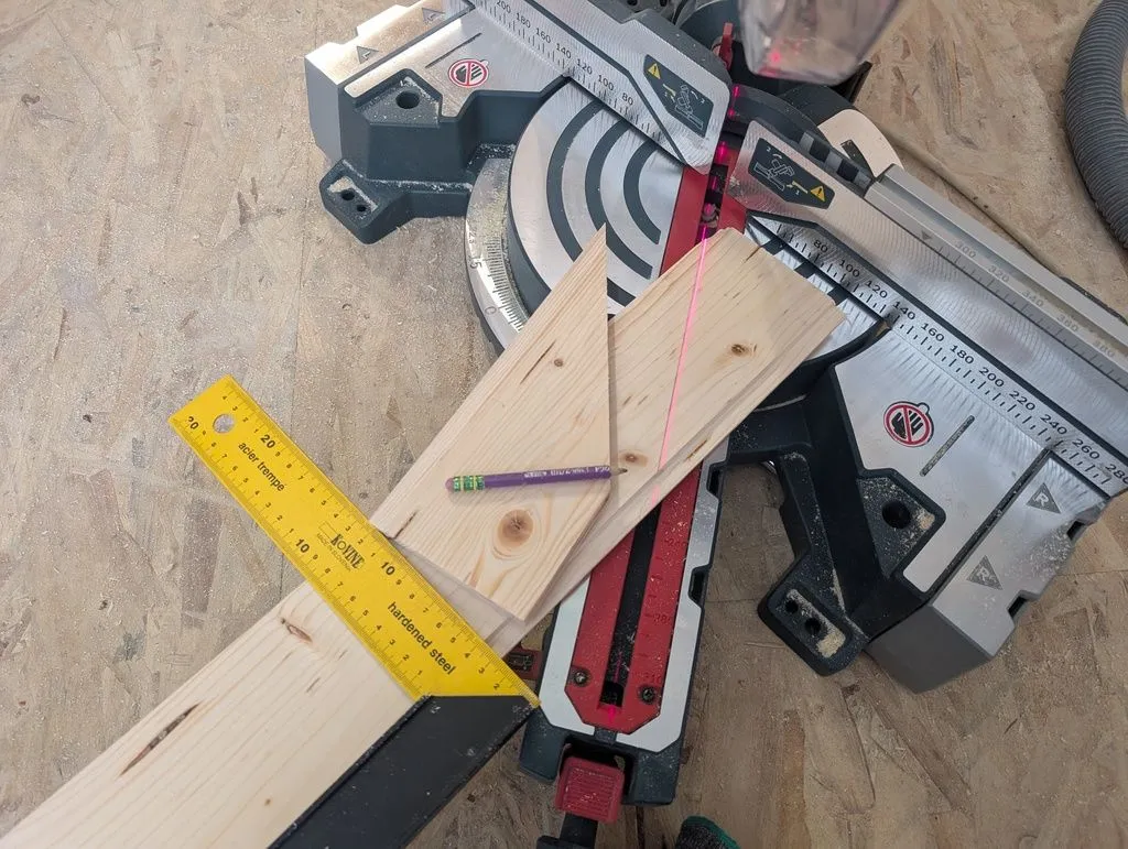
The miter saw proved invaluable for making the angled cuts needed to match the slope of the roof. (I didn't own a miter saw before, and bought one specifically for this job.)
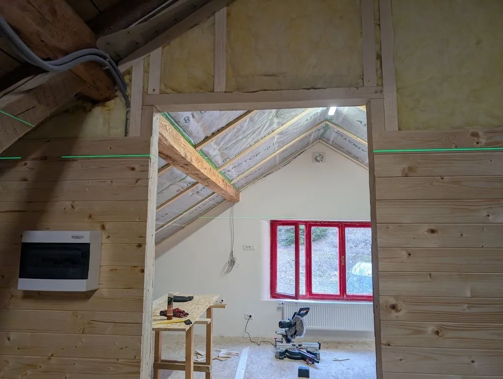
We used a laser level to ensure the boards were aligned on either side of the doorway.
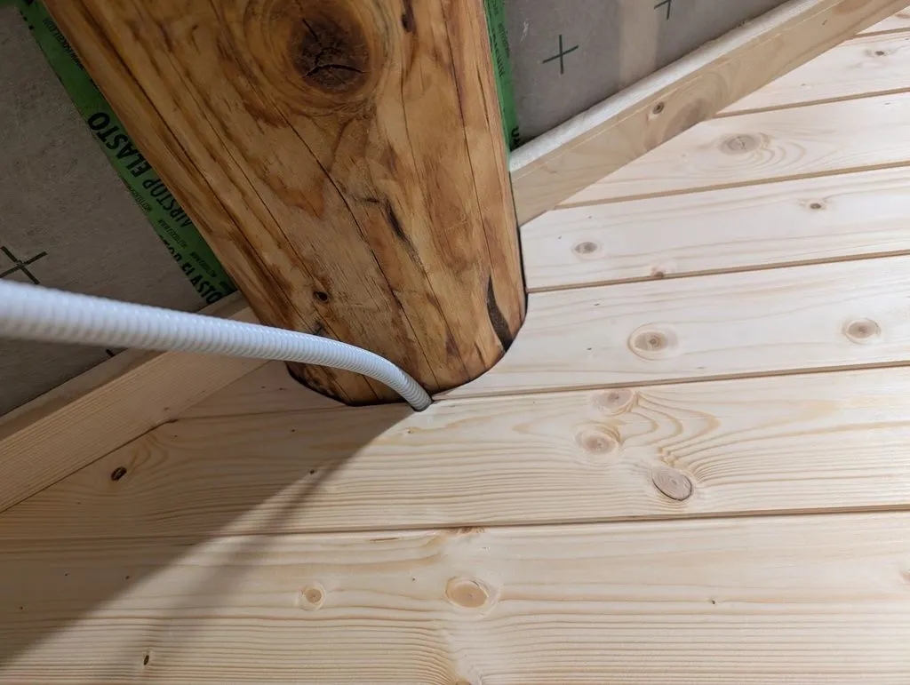
It took some scribing and jigsaw heroics to match the tongue and groove boards to the contours of the main structural beams.
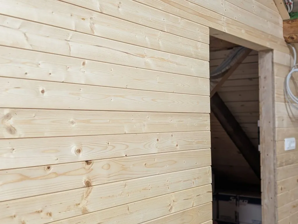
The completed tongue and groove finish on the interior wall.
Electrical part 1: Outlets and switches
Earlier in the job I first installed conduit and pulled cable to all of the electrical boxes and fixtures. The conduit runs along and is attached to the grid of wooden sleepers in the subfloor substructure. I apparently forgot to take pictures of the process of laying conduit, but you can see the finished job below.
We then installed the outlets and switches and made the necessary connections in intermediate junction boxes. Electrical boxes are installed differently in the Multipor walls and wood-framed walls, and I show examples of both below.
See the next section for the wiring of the panel.
Electrical cable is run in conduit along the grid of wooden sleepers in the subfloor substructure. The large bundle of cables in the foreground will enter the attic subpanel.
Outlets and switches in a Multipor wall
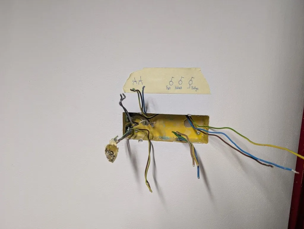
An electrical box in the Multipor wall to hold future outlets and switches. The box is fixed with gypsum-based plaster into a larger keyed hole cut into the Multipor wall. The Multipor itself is too brittle to reliably hold the box.
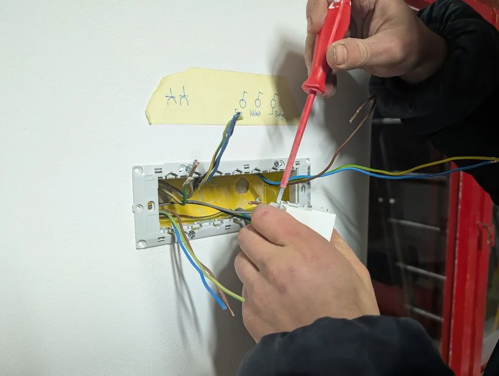
Making the electrical connections for the switch controlling the ridge light.
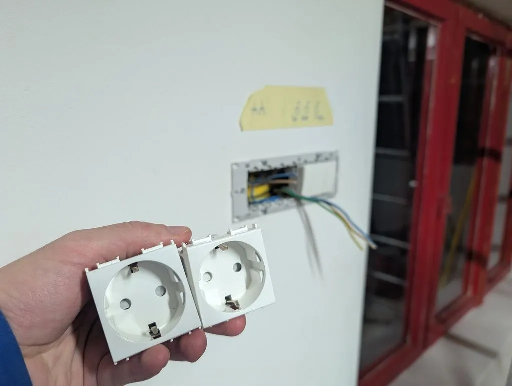
Switches installed, on to the outlets.
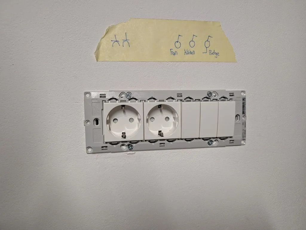
The outlets and switches click into the gray mounting frame with a (in my opinion) delightful modular clip/tab click-in system made by TEM Čatež, a local Slovenian electrical manufacturer. The system is modular, with an outlet taking up the width of two switches.
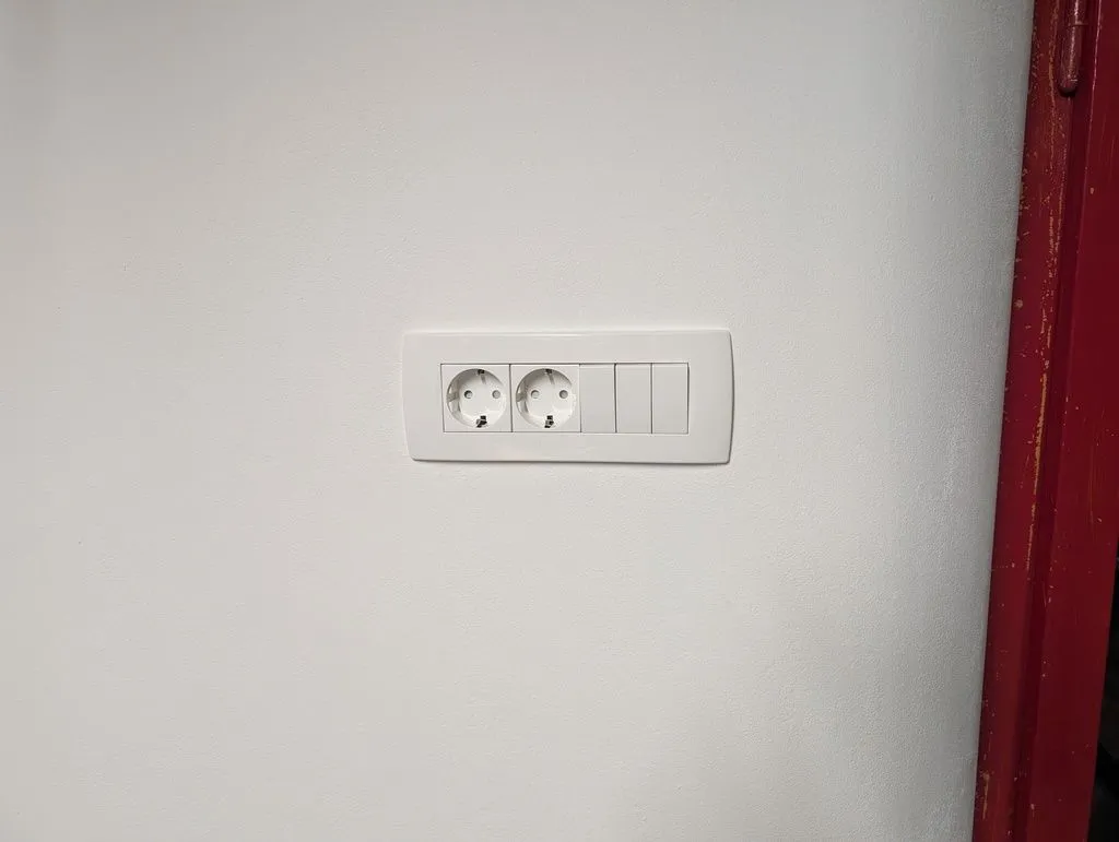
The completed outlet and switch box, with the cover plate installed.
Junction box in a wood-framed wall
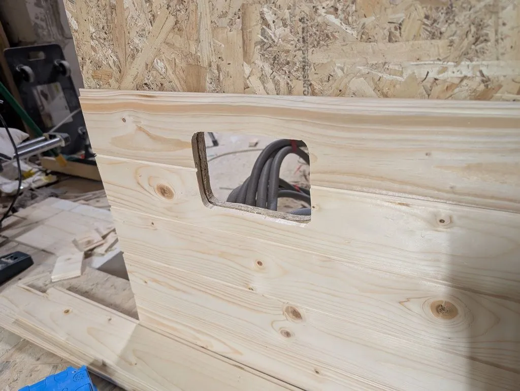
A hole matching the profile of the junction box is first cut into the wall's surface.
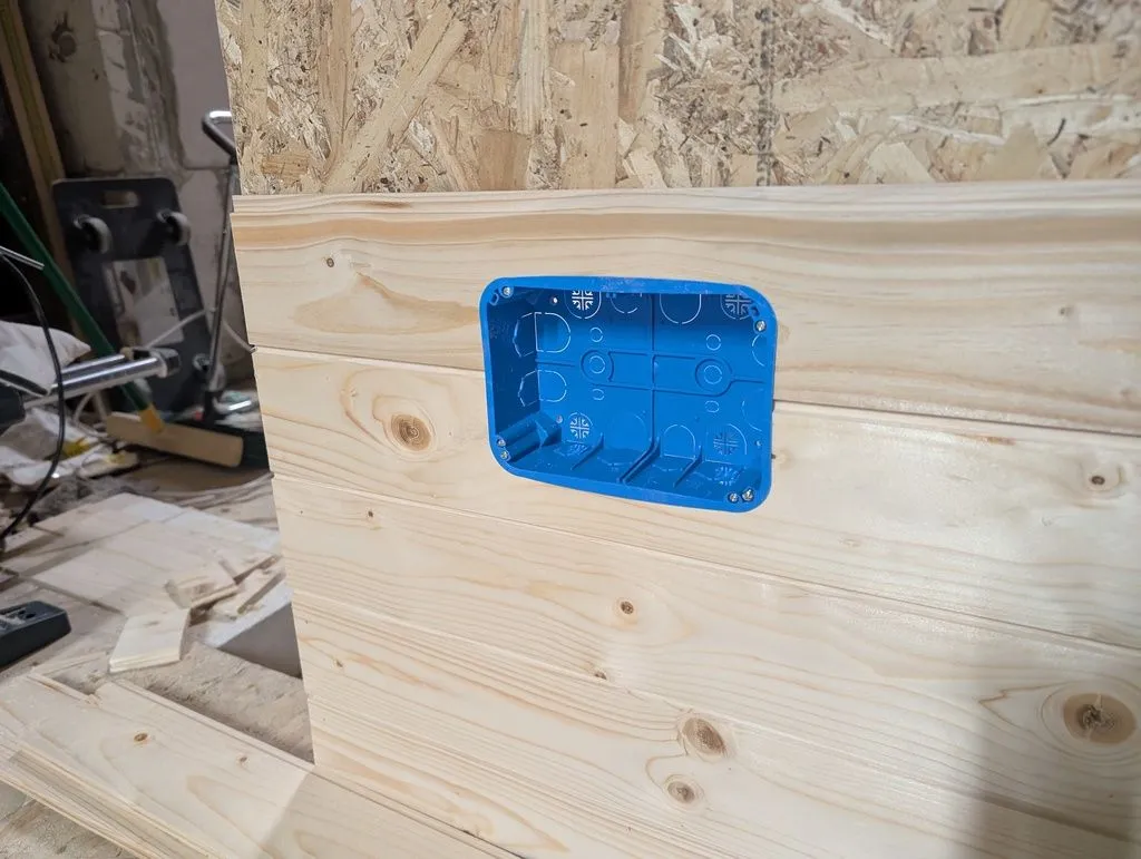
The box is held in place by mounting clips at the back, which are tensioned with screws at the front of the box to accommodate walls of varying thickness.
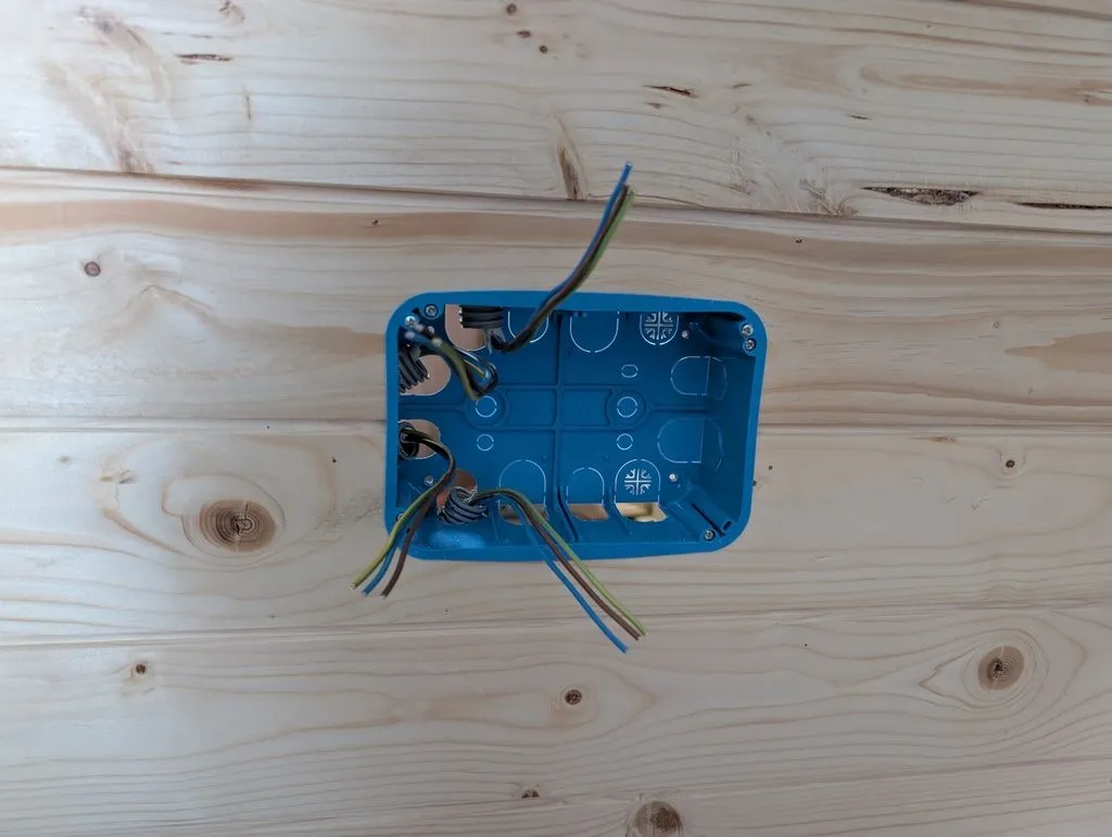
Pre-formed holes in the box make it easy to lead in electrical wiring from any direction. Above goes to the panel, down goes into the floor and on to the loads.
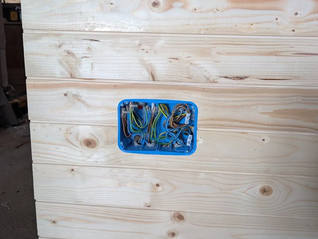
The wired junction box, which serves as a secondary distribution box from the main panel. The circuits from the main panel split off in this box and travel through the attic living space.
Wiring Ethernet jacks
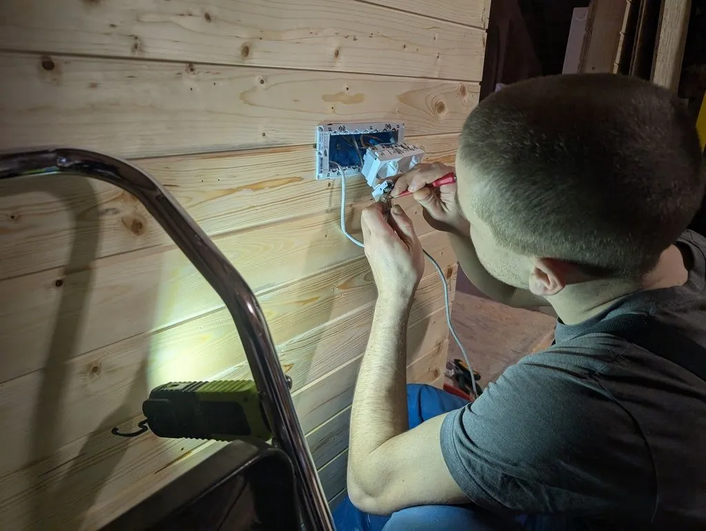
We also ran Ethernet cables to the apartment.
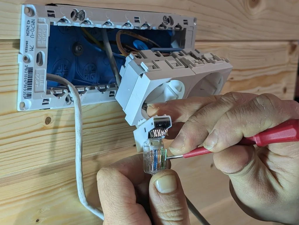
The Ethernet jacks have terminals for each of the eight conductors in standard Ethernet cable. Here I'm using a fine screwdriver to insert the conductors into their terminals.
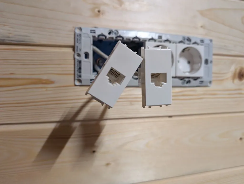
The Ethernet jacks wired up and ready for installation.
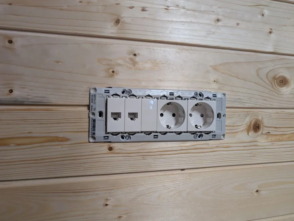
The Ethernet jacks use the same modular click-in system as the outlets and switches, so outlets and Ethernet jacks can live in the same electrical box.
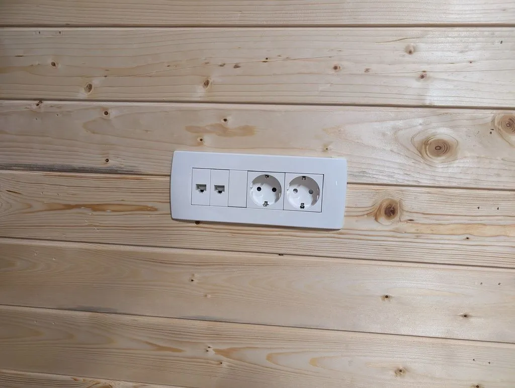
All done! Wiring complete and cover plate on.
Electrical panel
We installed a dedicated subpanel for the attic. The panel is supplied by three phases (we are fortunate to have three-phase power on the property) and has a dedicated RCD (FID switch in colloquial Slovene, serving the same residual current protection role as the GFCI outlets used in the USA) along with the usual miniature circuit breakers for overload protection.
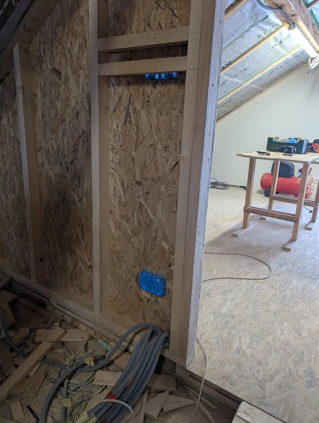
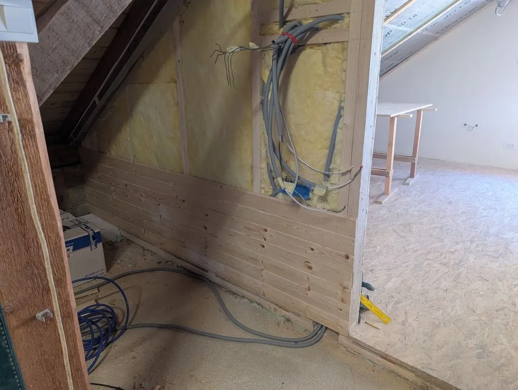
The two pieces of horizontal blocking in the stud wall will hold the electrical panel. Cable enters from below—you can see the collection of conduit at the base of the wall.
Conduit has been routed up to the future panel location and the wall insulated.
Installation of the tongue and groove wall finish in progress.
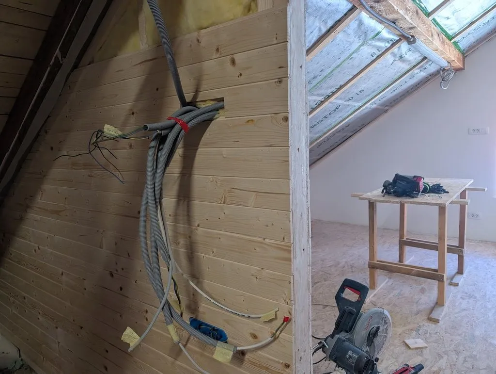
Tongue and groove wall finish done (at least to the height of the panel)! The panel is now ready to be installed.
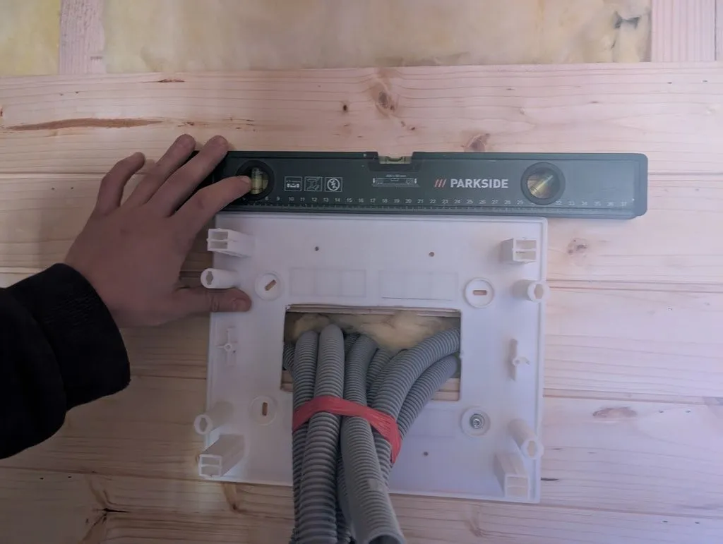
Ensuring the panel is level.
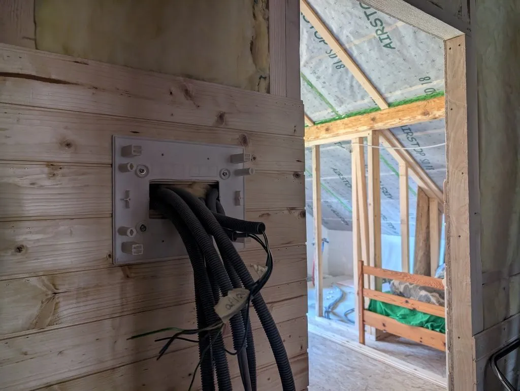
The panel's subframe attached to the wall, with conduit routed into the panel.
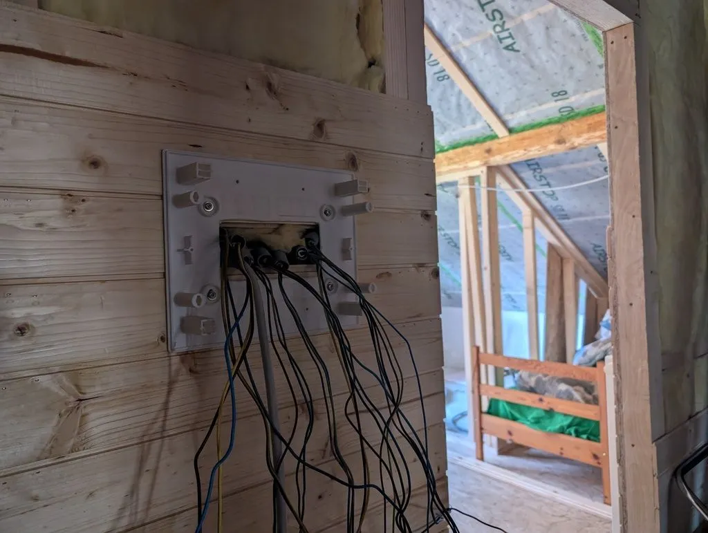
Conduit trimmed to length and outer cable sheathing stripped, exposing the individual conductors.
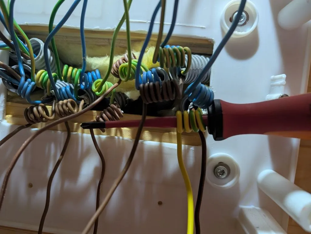
I added service loops to each conductor, which give you some extra wire in case of future modifications or rerouting.
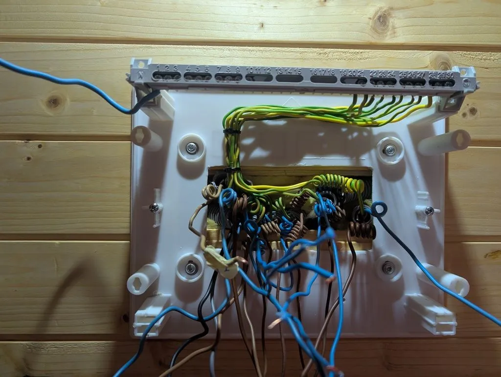
The ground conductors (yellow and green) routed to the ground busbar (top right). I'll then connect the neutrals (blue conductors) to the neutral busbar (top left), and finally install the circuit breakers and wire up the live conductors (brown).
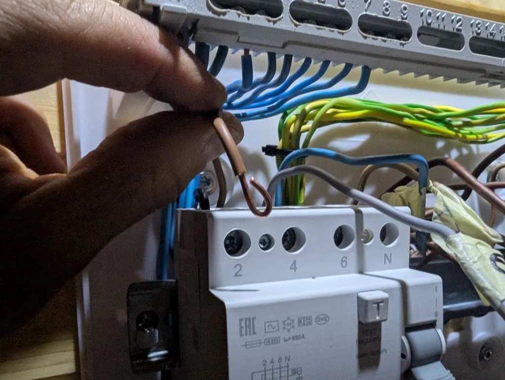
A hook at the end of the conductors (foreground) makes for a better electrical connection in the terminals. The device in the background with the 2/4/6/N terminals is the RCD, which also serves as the main shutoff switch for the attic's electrical supply.
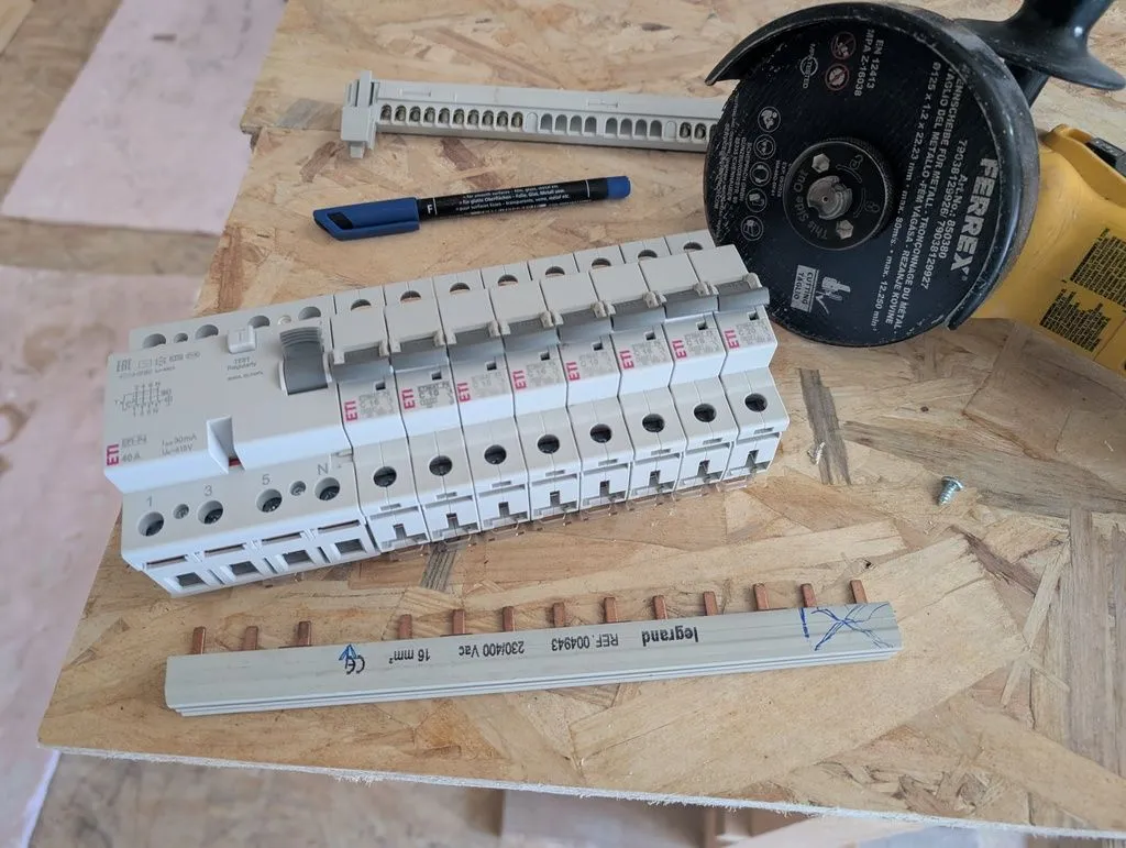
A copper rail (bottom, with projecting copper teeth) connects the supply (from the RCD, the larger device at the left) to the individual miniature circuit breakers (the smaller devices towards the right). Although barely visible from the picture, there are in fact three separate, electrically insulated rails, one for each phase of the three-phase supply. The teeth in the rails connect to terminals in the bottoms of the breakers. The missing tooth at the fourth-from-left position is intentional, so as to avoid the neutral (N) terminal in the RCD.
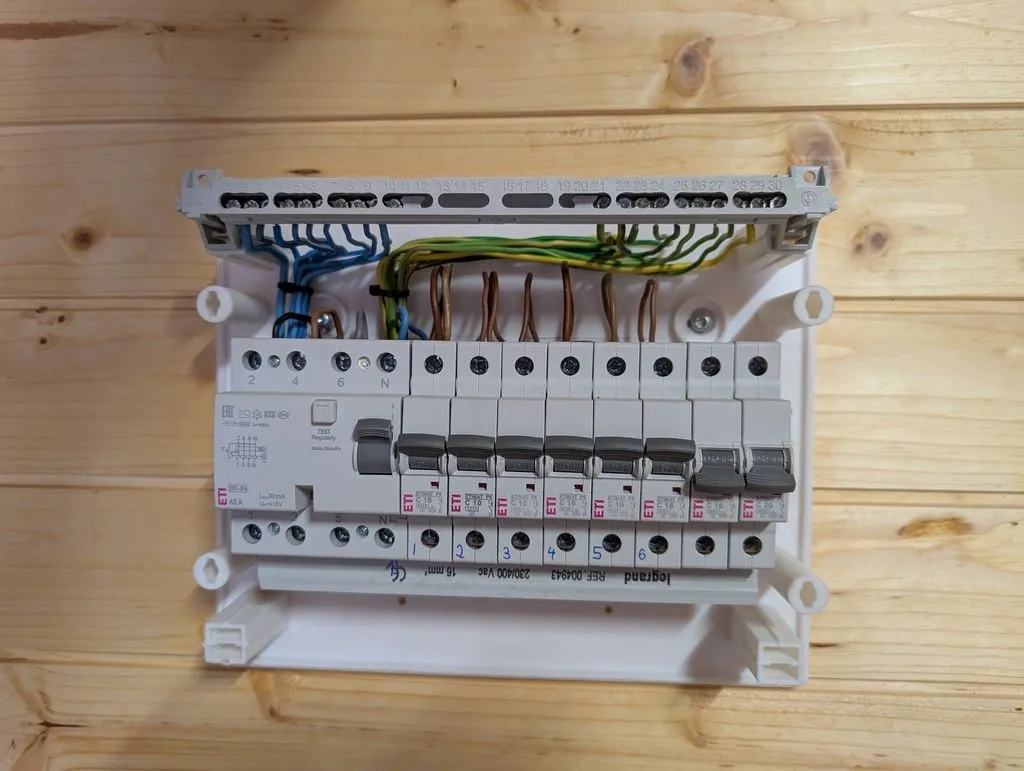
Wiring complete! The blue conductors at left are neutral, the green/yellow conductors are grounds, and the brown conductors coming out of the circuit breakers are live. The two breakers at right are unused extras for future use.
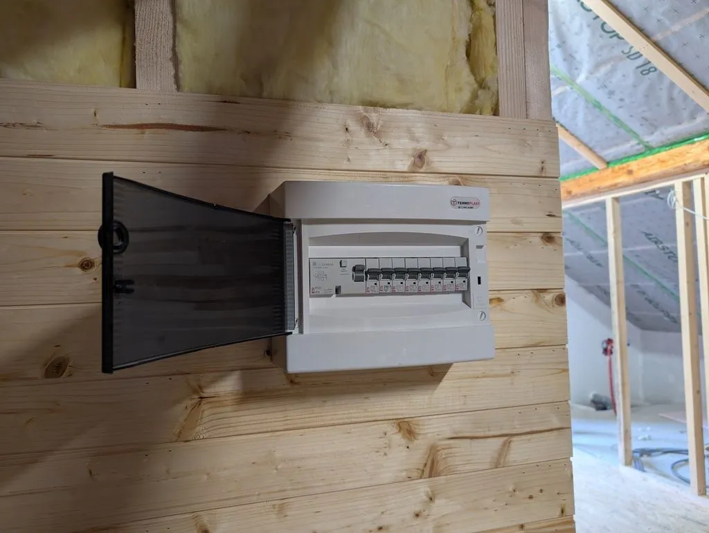
The completed panel with the cover on.
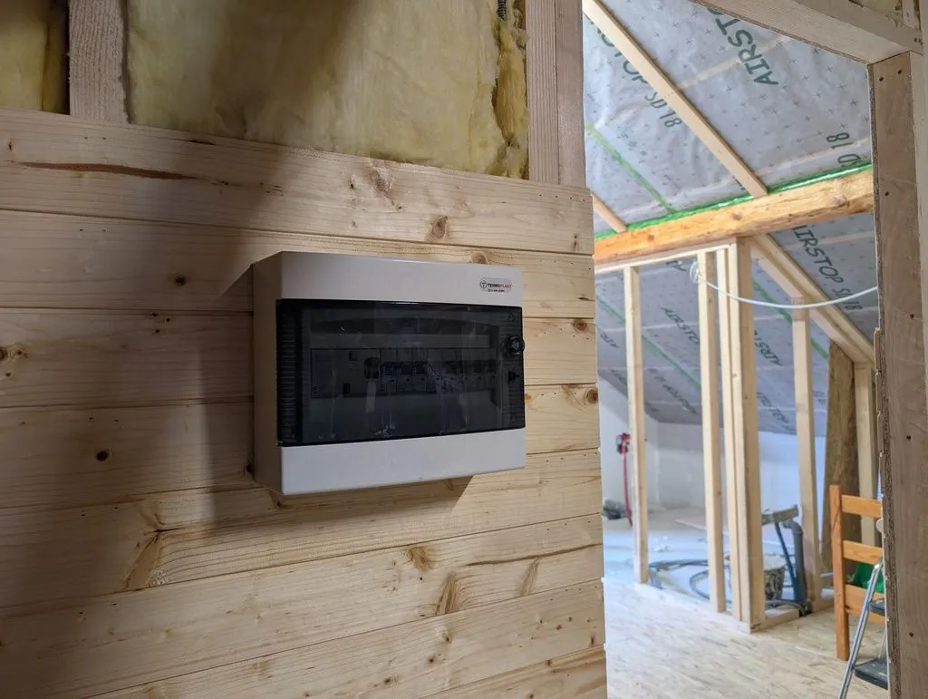
All done!
Tongue and groove ceiling finish
The original ceiling in the attic came with a nice tongue and groove finish. We removed this and set it aside at the very start of the project so as to insulate the ceiling. With the ceiling insulated, it's now time to reinstall the ceiling finish.
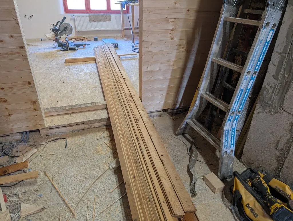
The original tongue and groove ceiling boards, ready for reinstallation.
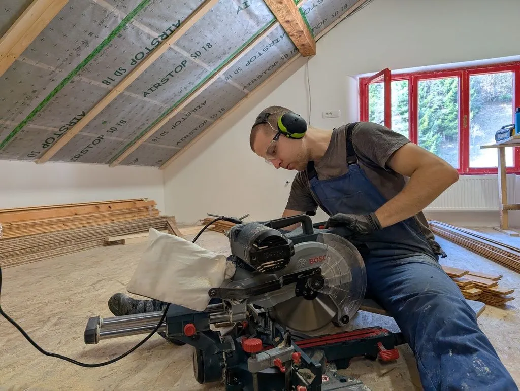
Cutting the boards to length on the miter saw.
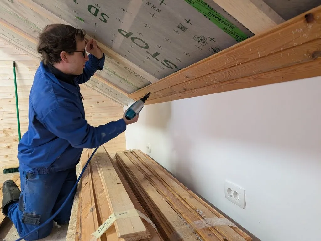
Martin helped throughout the ceiling finish process. Here he is attaching the first few boards with an 18 gauge pneumatic brad nailer.
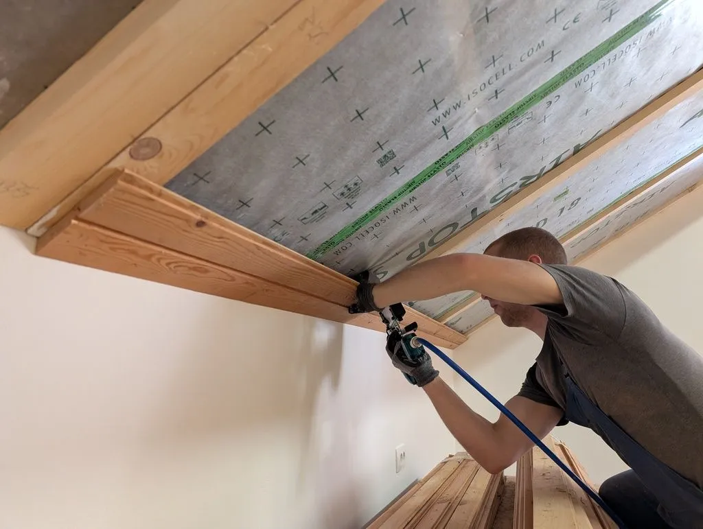
Nailing a starter course in place...
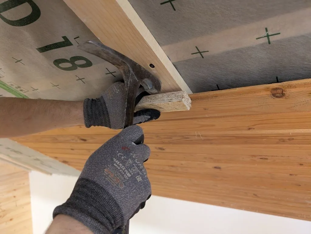
We used a jig made from a piece of tongue and groove OSB to fit the boards tightly. (Hitting the boards directly with a hammer would cause them to split, but the OSB jig fits over the boards and distributes force sufficiently safely.)
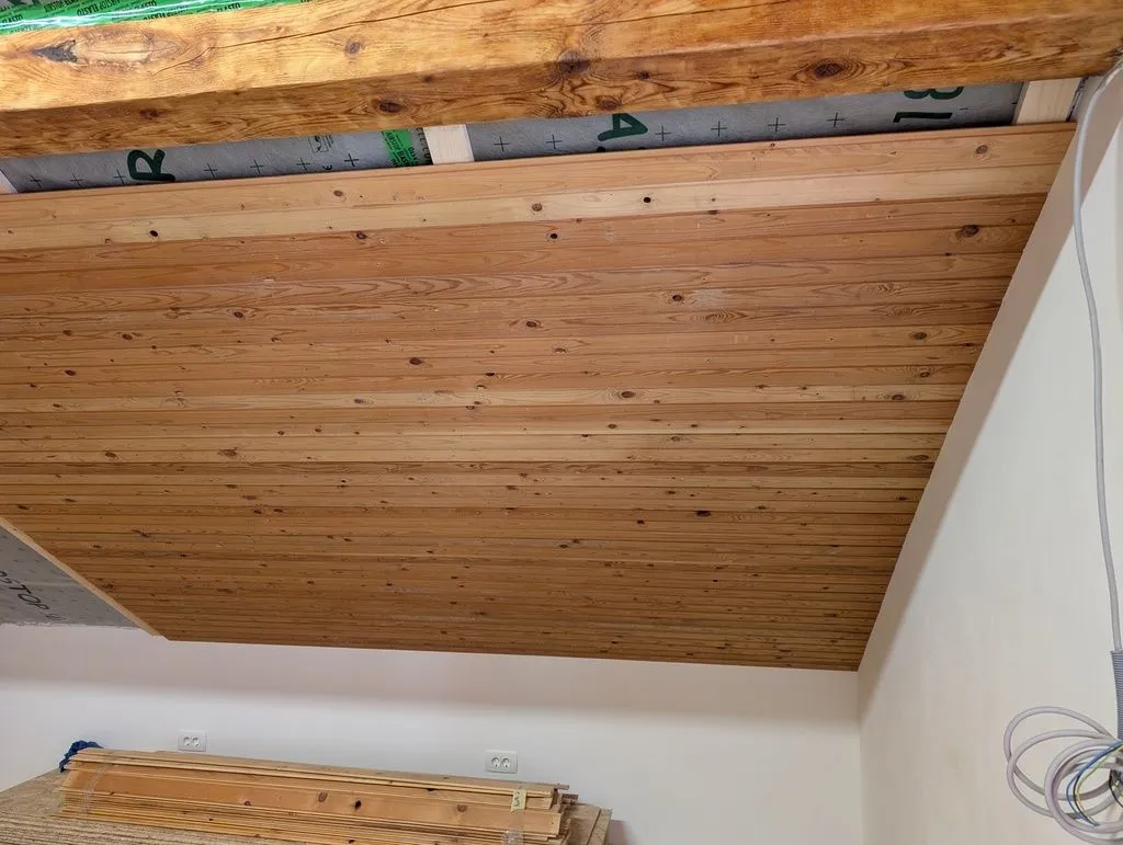
The first bottom sector almost complete!
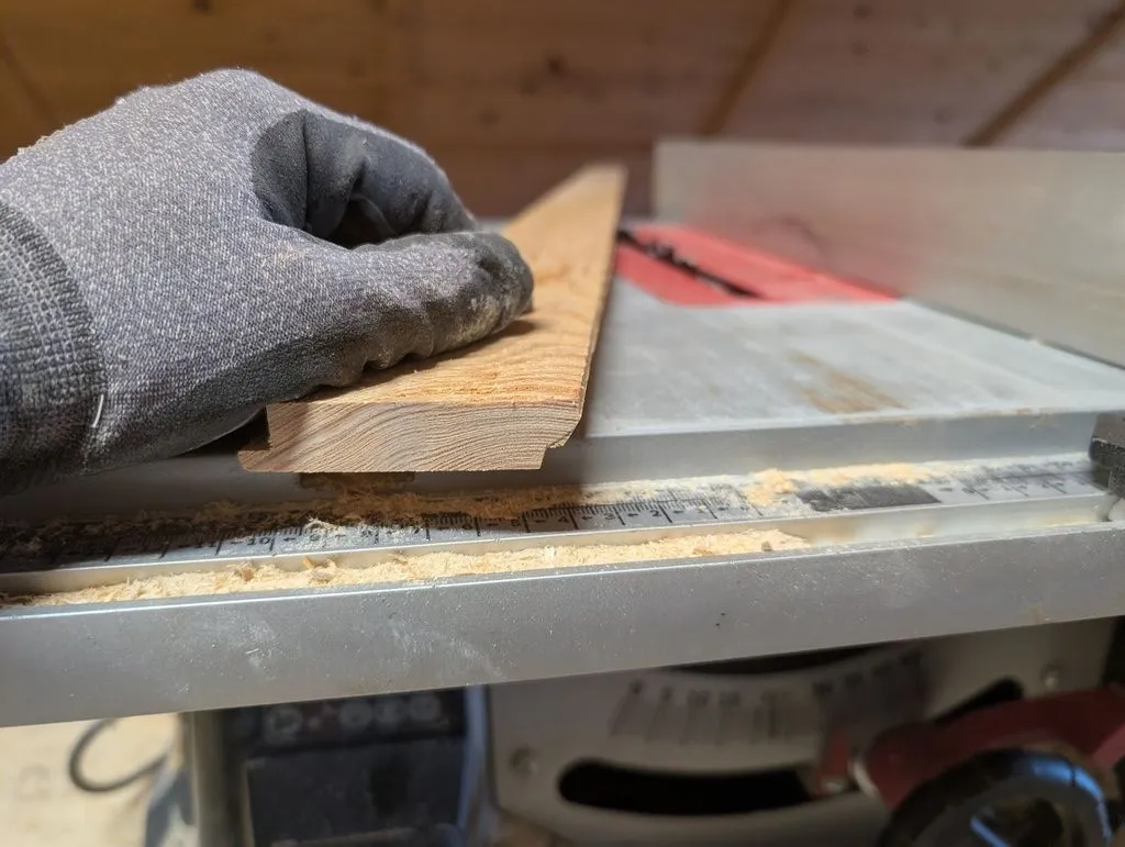
The first and final pieces need to be beveled to match the slope of the ceiling.
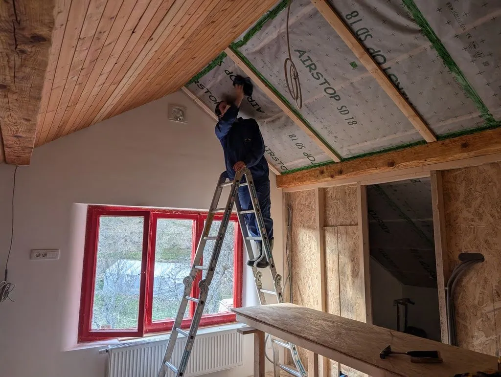
Martin wiping down the ceiling before installing the tongue and groove boards.
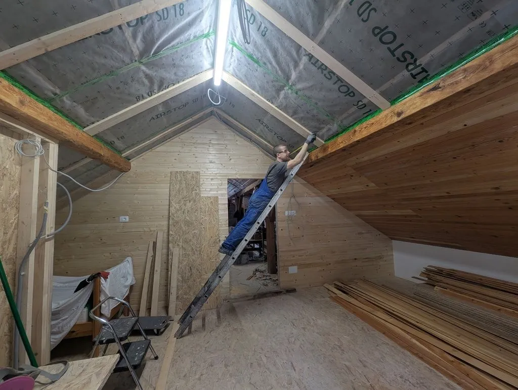
Our not-quite-OSHA-approved setup for reaching the start of the top sector. (I didn't lean the ladder higher up the ceiling at a more comfortable angle because it would risk puncturing the vapor barrier, which has only soft insulation underneath. Although I'm not sure why we didn't use a self-supporting A-frame ladder; perhaps we were playing around intentionally.)
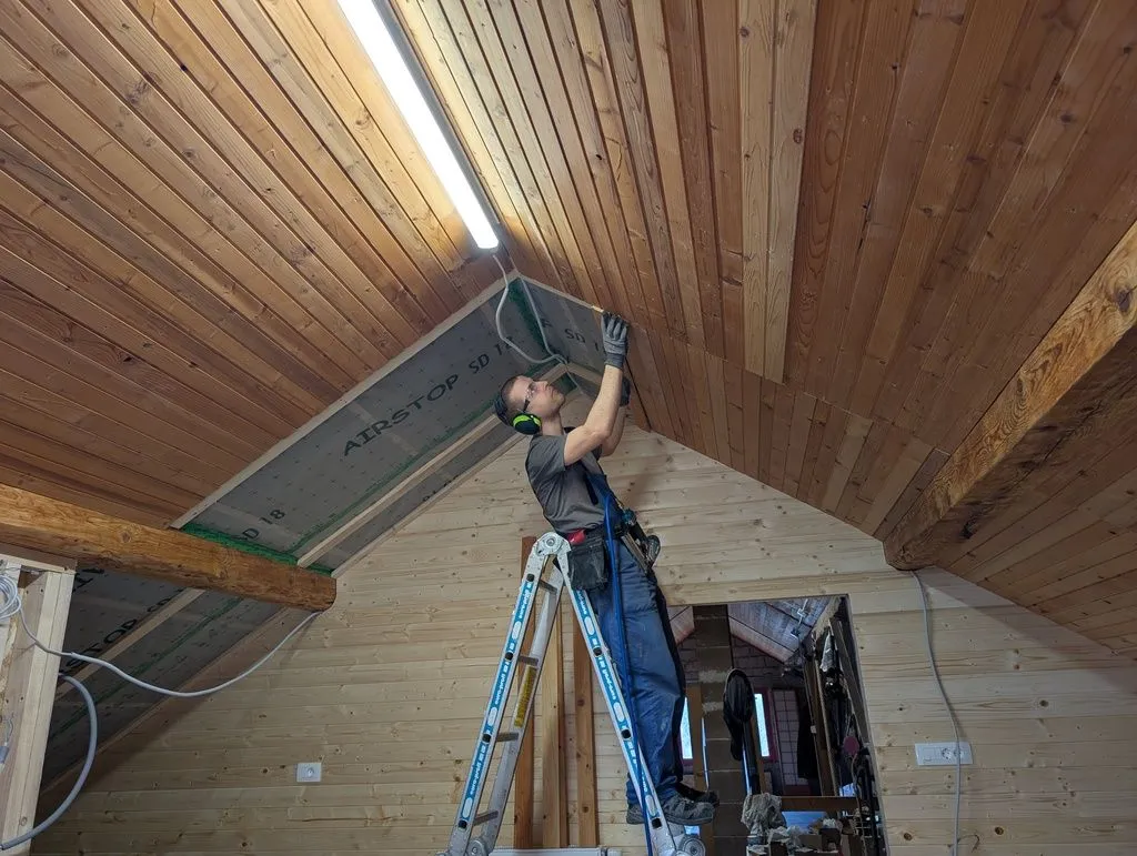
Here we've brought out the more sensible A-frame ladder.
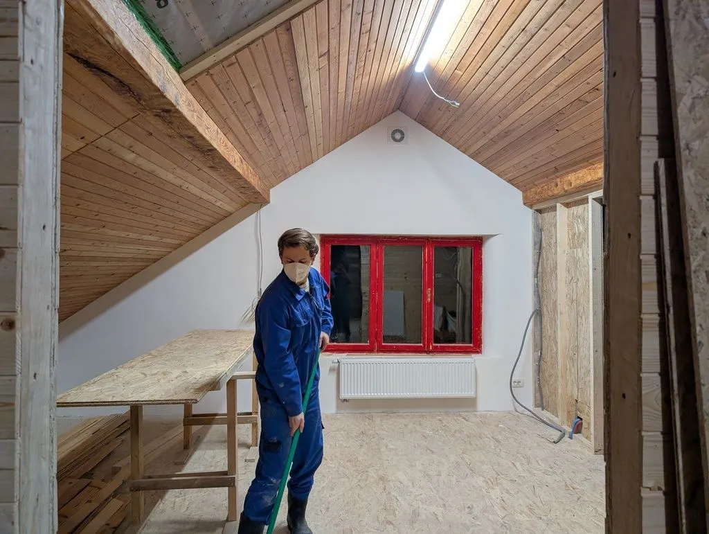
Almost done! Martin is sweeping away sawdust and residual construction waste before wrapping up for the day.
Ceiling ridge lights
We installed recessed lights along the length of the ceiling ridge. We first built out a lowered "soffit" at the top of the ridge, which created a flat cavity, into which we could then run cable and install the recessed lights. The lowered soffit also provides a cavity for ventilation of the LED lights' drivers—according to the manufacturer, the lights should have at least 50 mm (2 inches) clear space above.
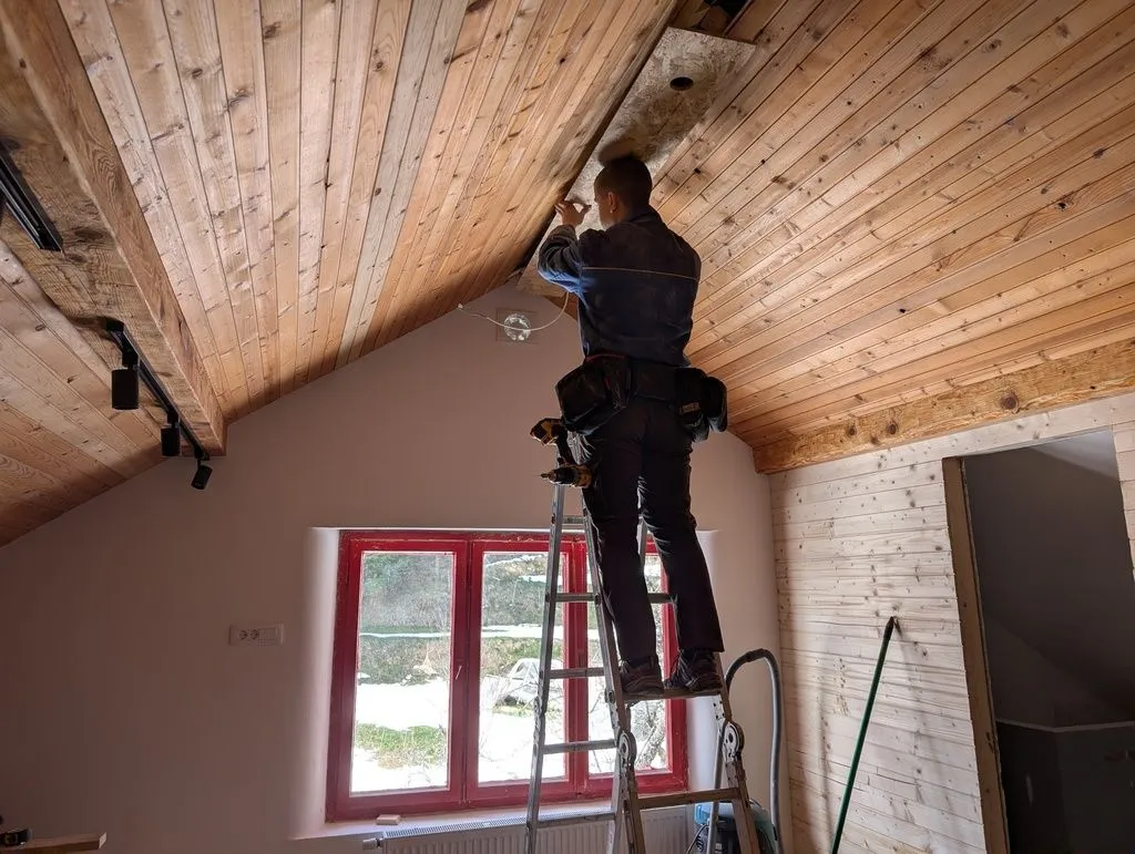
Test-fitting the OSB soffit that creates the cavity at the ridge into which we will recess the lights.
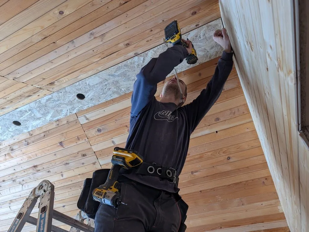
Attaching the soffit to the ridge.
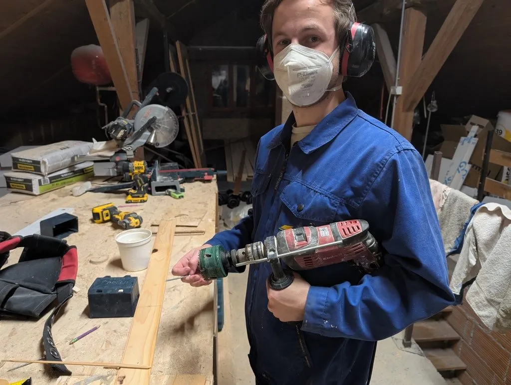
Martin with the drill and hole saw we used to drill the holes that would hold the recessed lights.
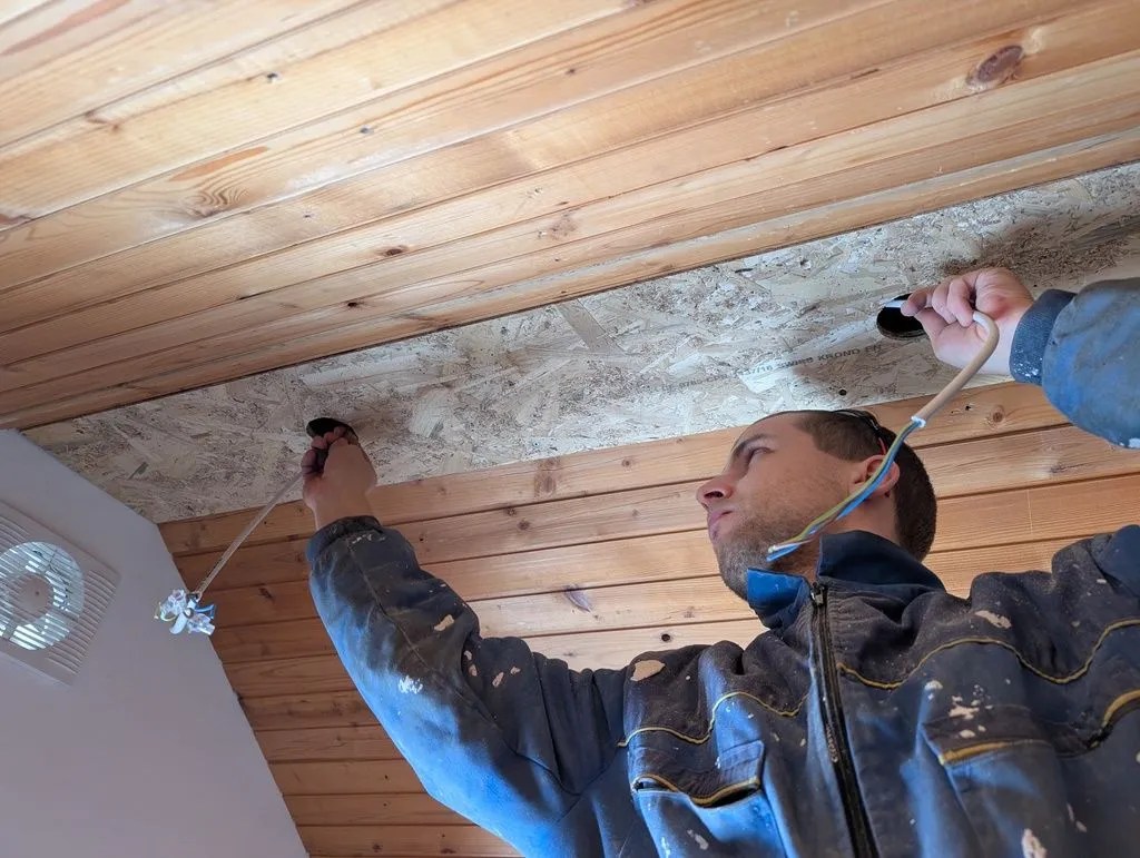
Running electrical cable from hole to hole to power the lights.
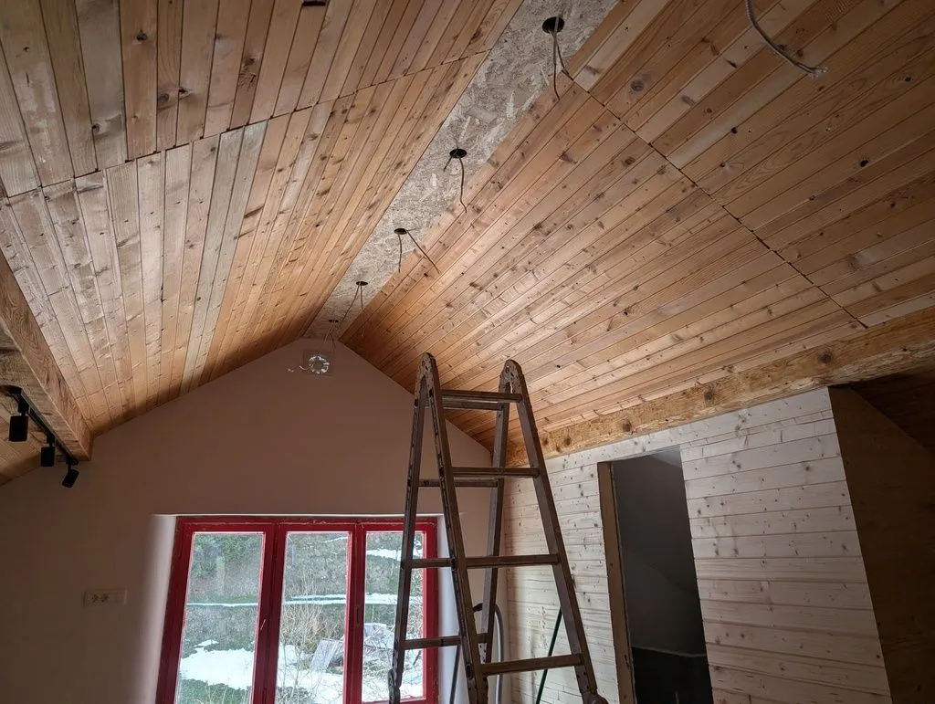
Completed cabling, with stub-outs protruding from the light holes, ready to supply the lights.
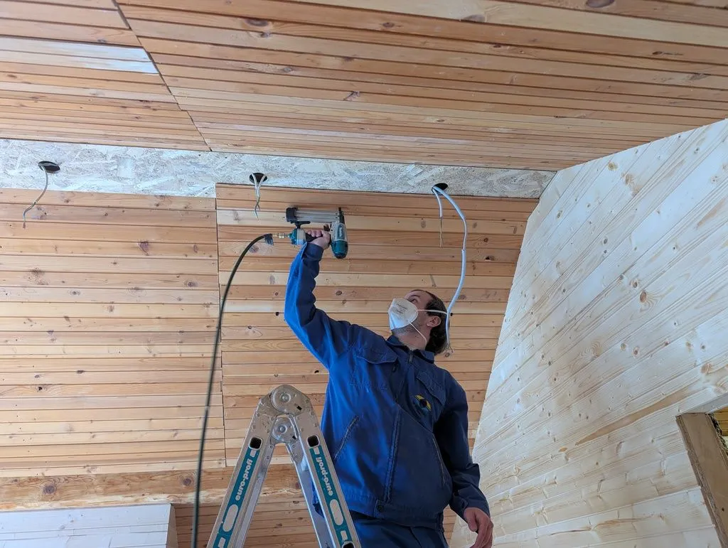
Martin attaching tongue and groove finish ceiling to the OSB soffit.
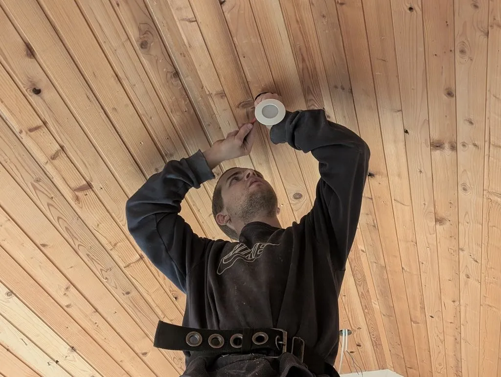
Wiring the recessed lights.
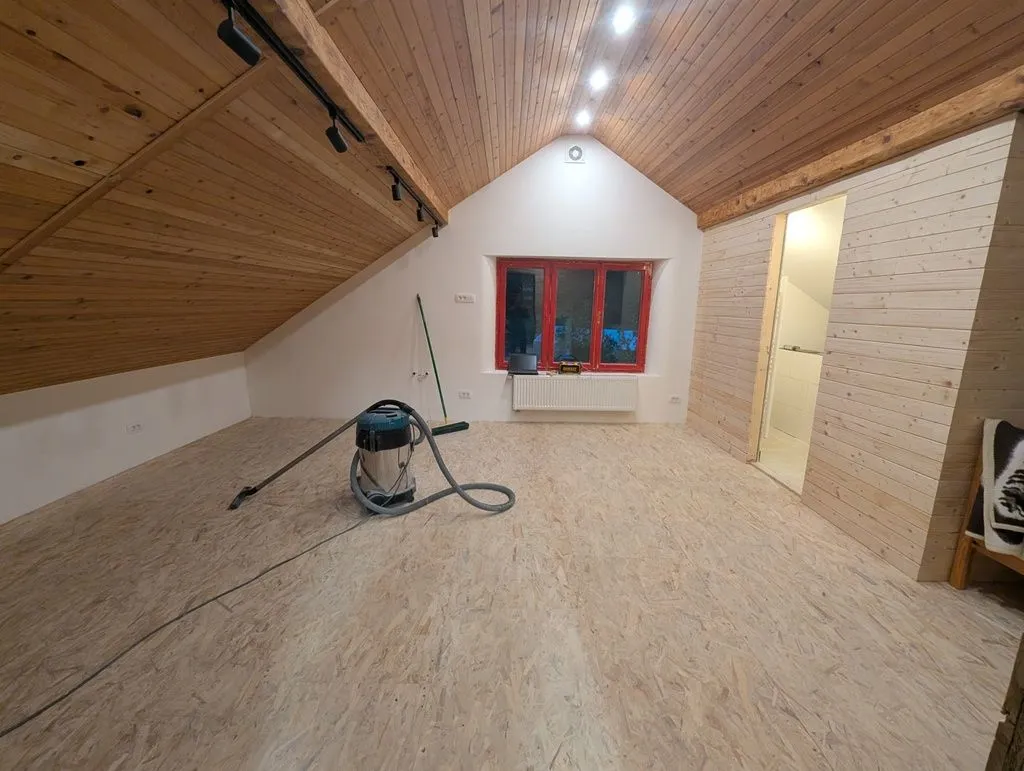
Jumping ahead a bit, here are the completed overhead lights.
Track lights along beams
We installed track lights along the attic's main structural to serve as accent lights. The lights can slide along an aluminum track mounted on the beams, and can also pivot on a ball joint.
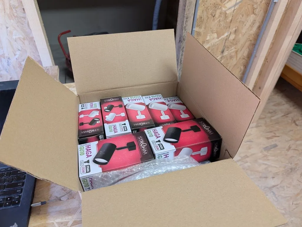
The freshly-delivered track lights, still in their original packaging.
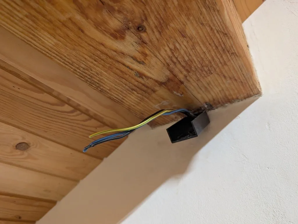
Electrical wire comes out of the wall at the beam to supply the track lights.
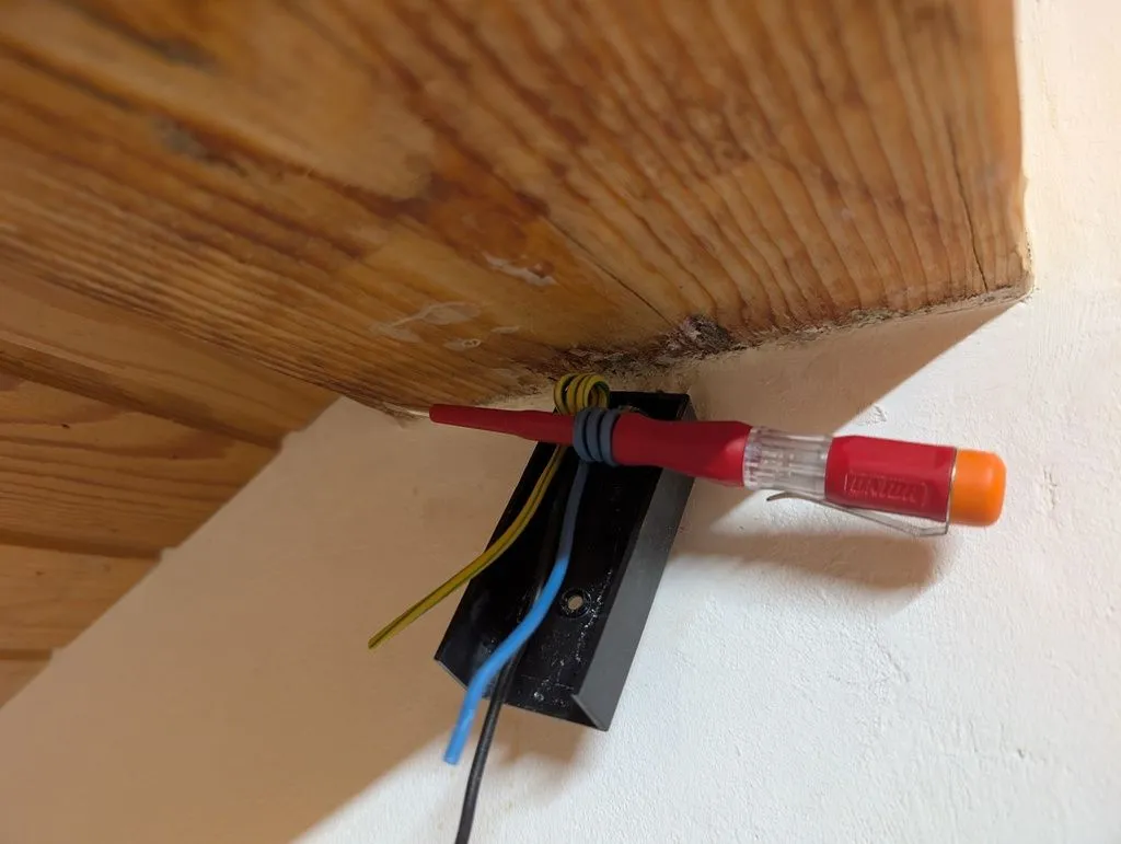
Adding a service loop to the wire (the loop gives some extra length in case of future maintenance or rewiring).
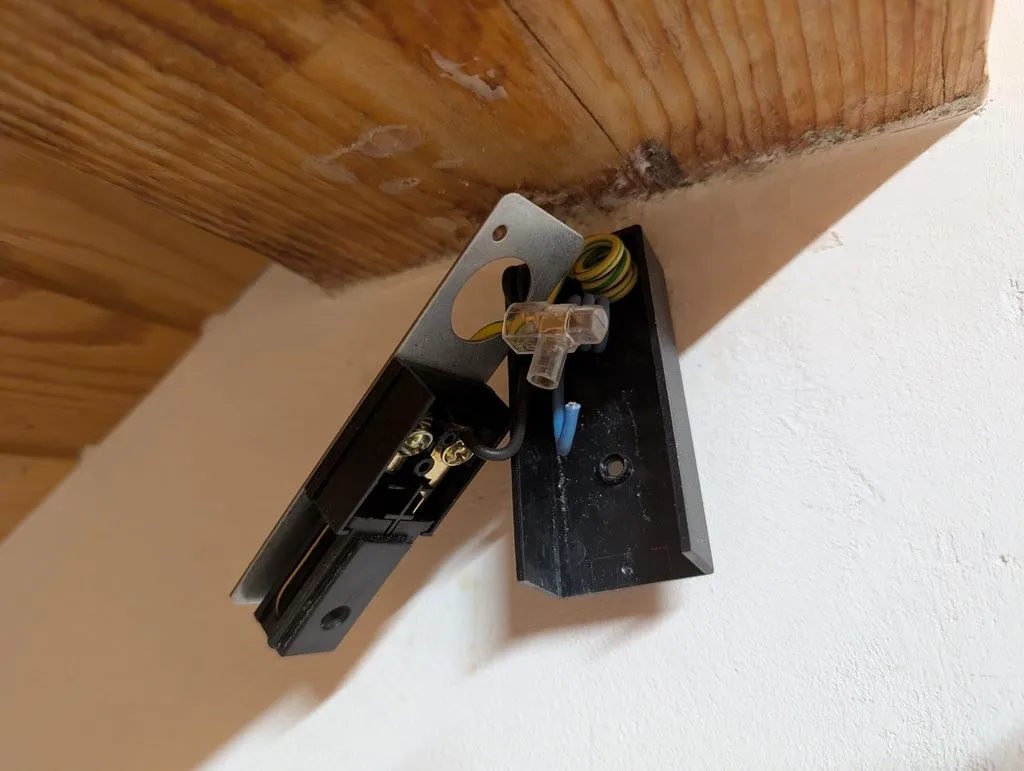
Making the connections to the terminal block that powers the track lights.
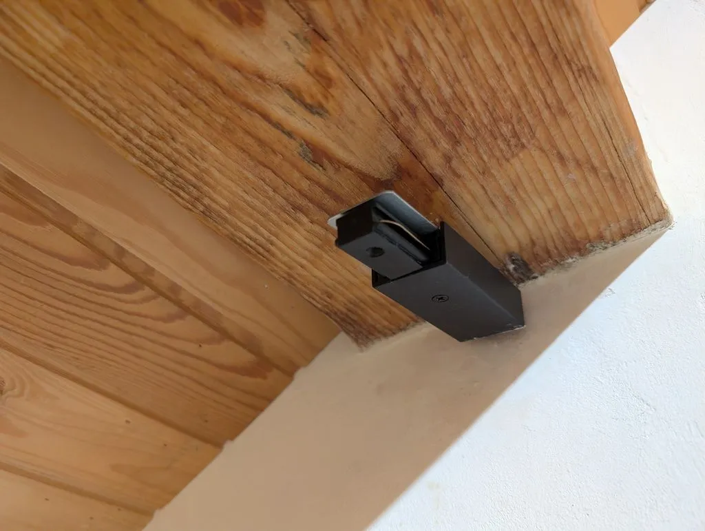
The completed terminal block—you can see the protruding copper tabs, which attach to copper rails in the track.
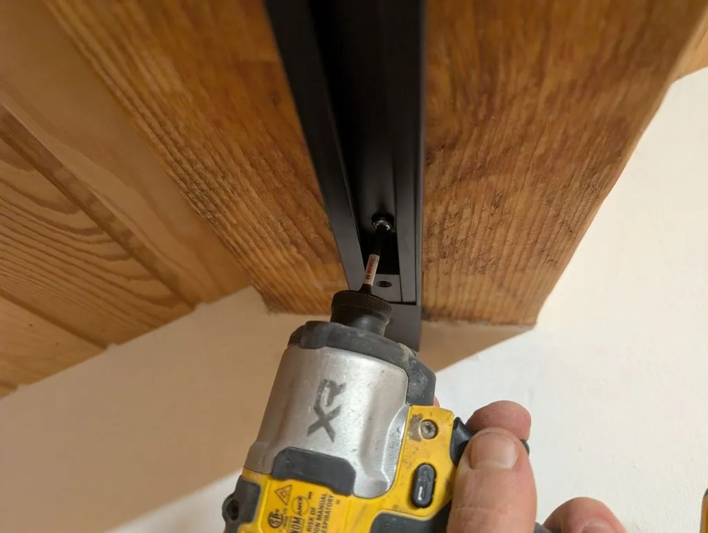
Attaching the track to the beam.
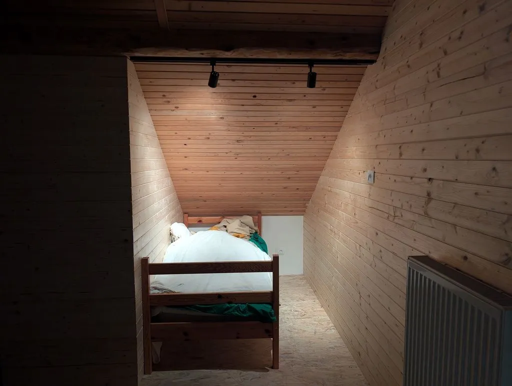
The installed track lights. A three-way switch by the bed lets you turn the lights off from in bed.
Start of bathroom work: closing off the toilet frame
We installed a hanging Geberit toilet, which has the flush tank and plumbing hidden in the wall. Here I'm walling off the structural frame on which the toilet will hang with aerated concrete blocks.
Disclaimer: this step was actually done much earlier in the job, before finishing and painting the west wall, but I'm including it here as we begin a large section on the bathroom.
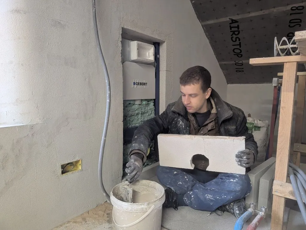
We walled off the toilet frame with aerated concrete blocks.
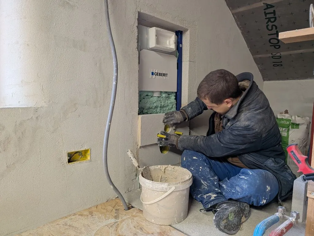
Fitting the blocks over the protruding plumbing and mounting brackets.
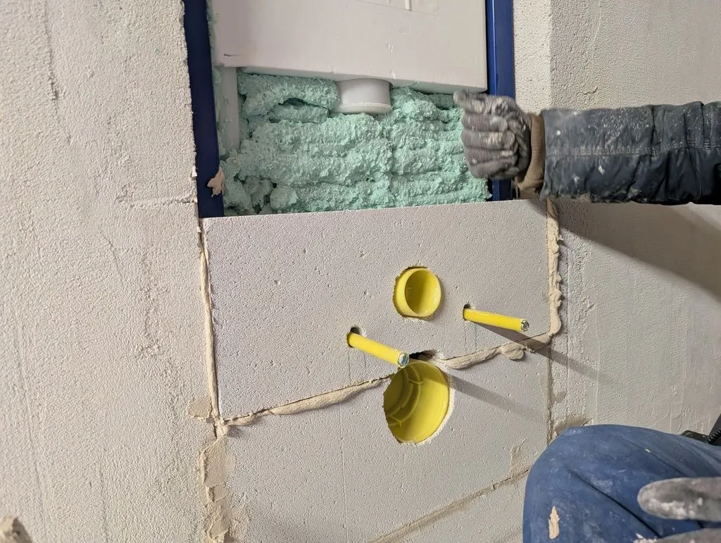
The aerated concrete blocks are attached with a mortar-like adhesive. Here I'm tapping down on the block to ensure a good mortar bond.
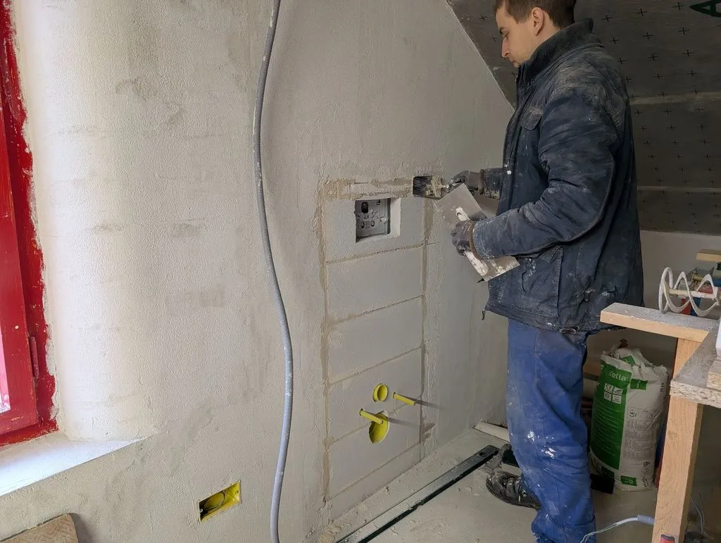
Finishing off the edges around the walled-off frame.
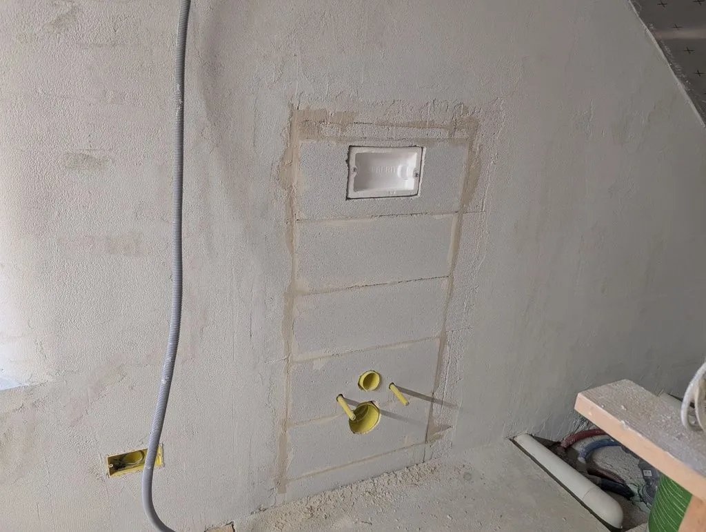
All done! The wall is now ready for a finish coat and painting (see earlier sections).
Laying the bathroom screed floor
We poured roughly 50 mm of cementitious screed (like concrete, but with smaller aggregate and nonstructural) for the bathroom floor on top of a layer of XPS. The XPS and screed together provide the height necessary for running plumbing in the floor with adequate fall/slope in the drain lines.
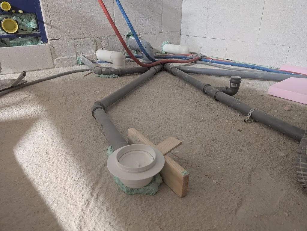
The plumbing in the bathroom floor, which will be covered by screed.
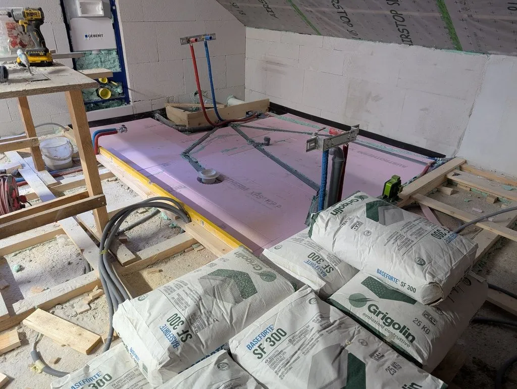
We first placed 50 mm XPS over the floor (we use a bottom layer of XPS instead of screed all the way down because it lessens the dead load on the ceiling below, and because it is cheaper and easier to install). The black tape around the perimeter of the bathroom is a foam-like material that serves as an isolation joint for the screed.
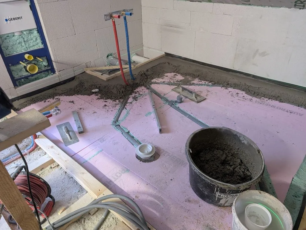
The first of the cementitious screed being laid on top of the XPS. We first establish level around the perimeter, then fill in towards the center.
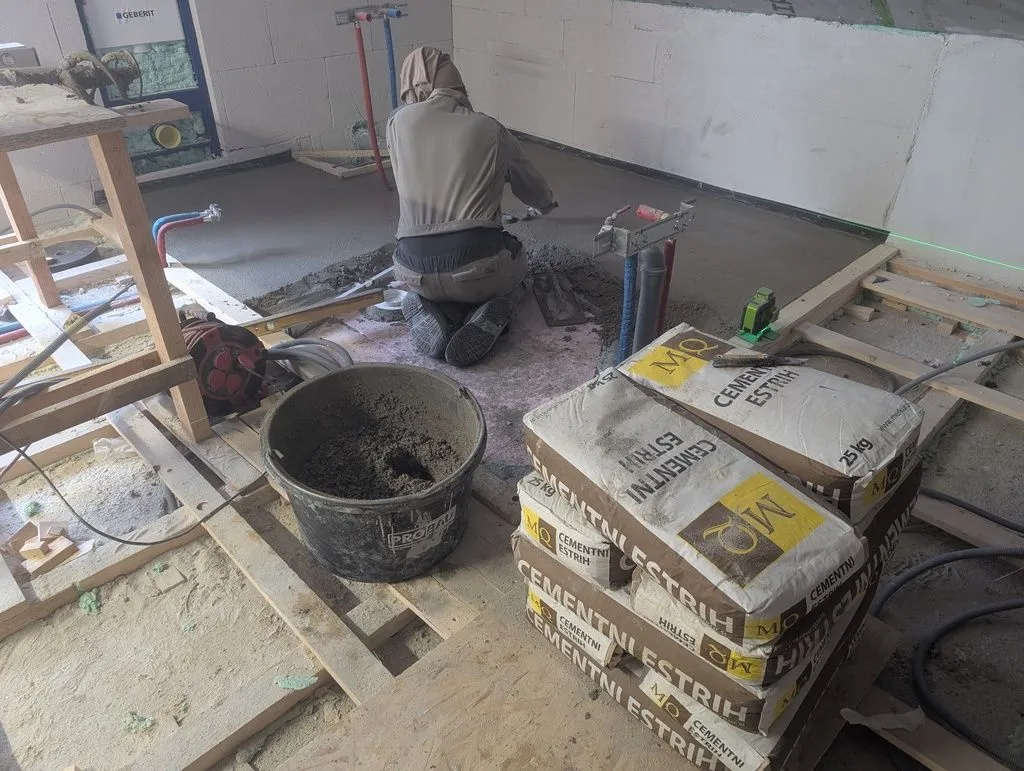
My cousin Anže, who was a crucial help during a few critical phases of the project, including the first phase of bathroom work. Here he is leveling out the screed.
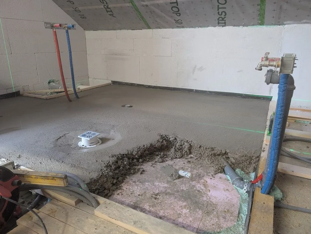
Nearing completion, only the final corner remains...
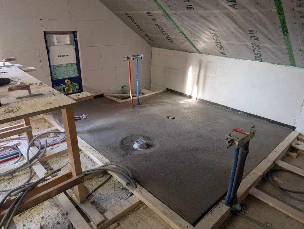
All done! The completed screed floor. We will later pour self-leveling compound over the screed and then tile the floor.
Framing the bathroom
The bathroom is framed with standard stud-wall construction and sheathed with 12.5 mm tongue and groove OSB.
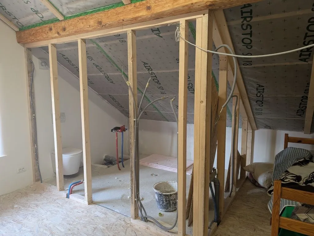
The framed bathroom walls. The conduit running up the studs will supply the bathroom lights, ventilation fan, and outlets.
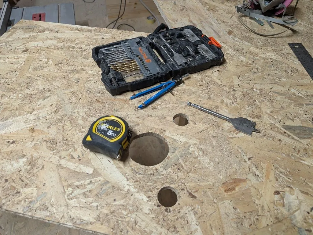
We drilled holes in the OSB sheathing to fit over plumbing lines.
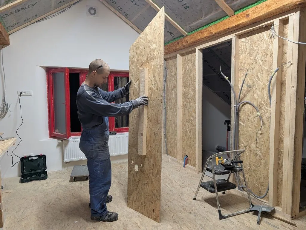
I attached a temporary "handle" to the back of the final piece of sheathing to allow me to maneuver it into place.
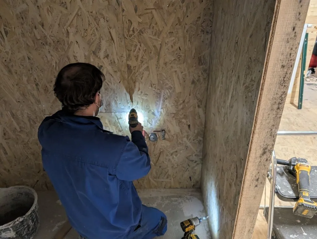
Martin helped throughout sheathing of the bathroom walls. Here he is attaching the final board.
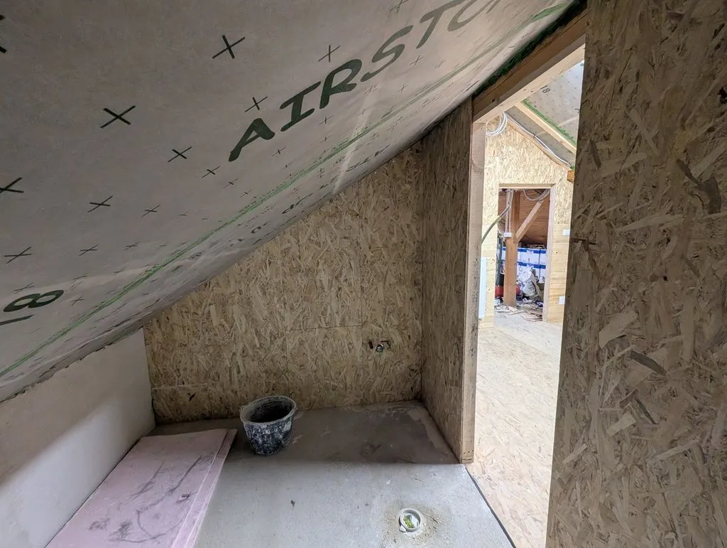
All done! The bathroom sheathing completed.
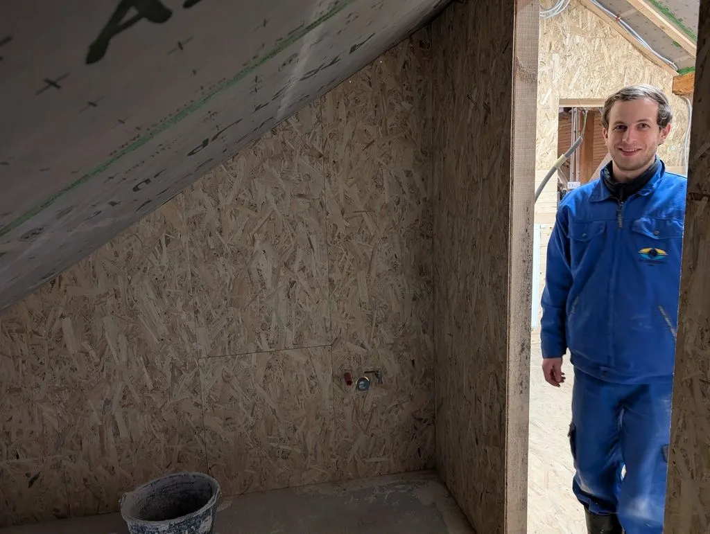
Martin, happy with a job well done!
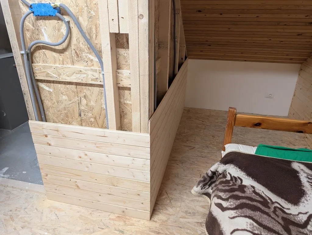
Attaching the tongue and groove finish to the exterior of the bathroom walls. At this point I had also installed the electrical box (blue box in top left) holding the bathroom light switches and outlets.
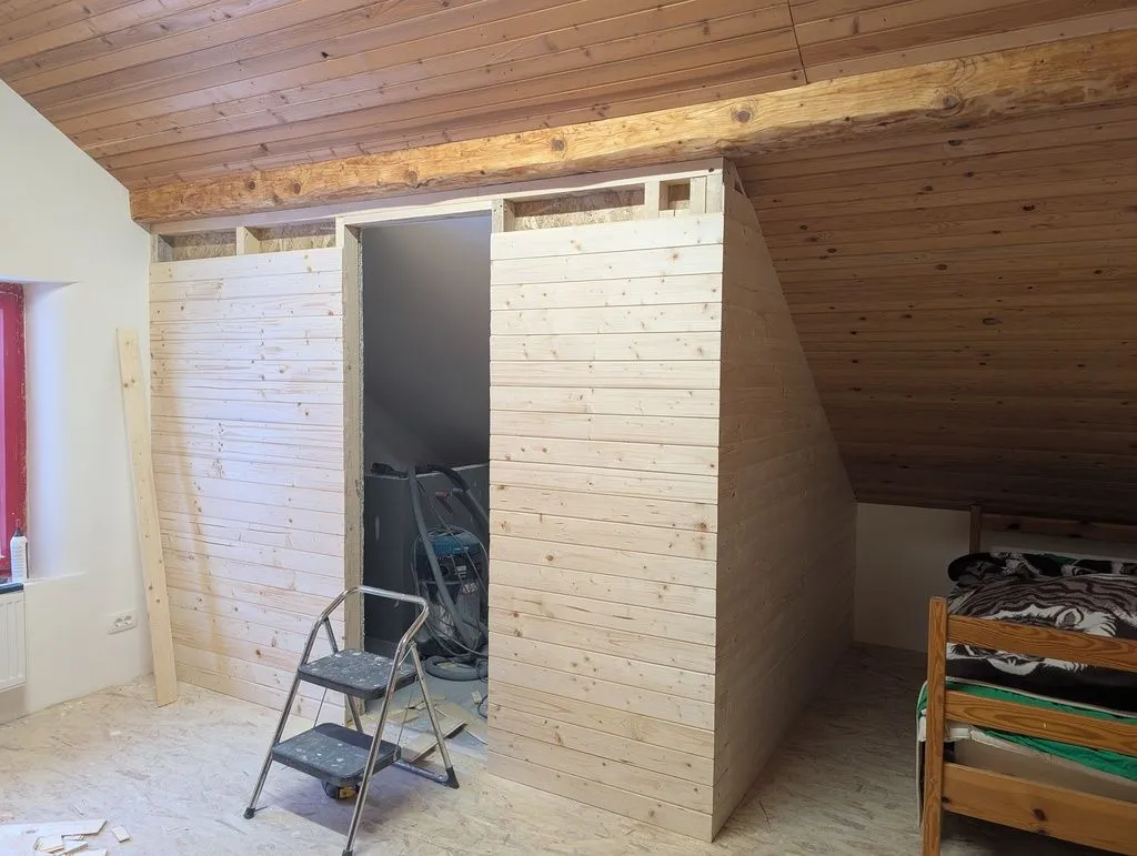
Almost done with the exterior bathroom wall finish.
Interlude: walling off the bathroom utility area
We walled off the plumbing area in the far corner of the bathroom with a hip-height "pony wall" built from aerated concrete block. The wall also holds the hot and cold water lines for the future bathtub. The walled-off area will later be covered and serve as a shelf.
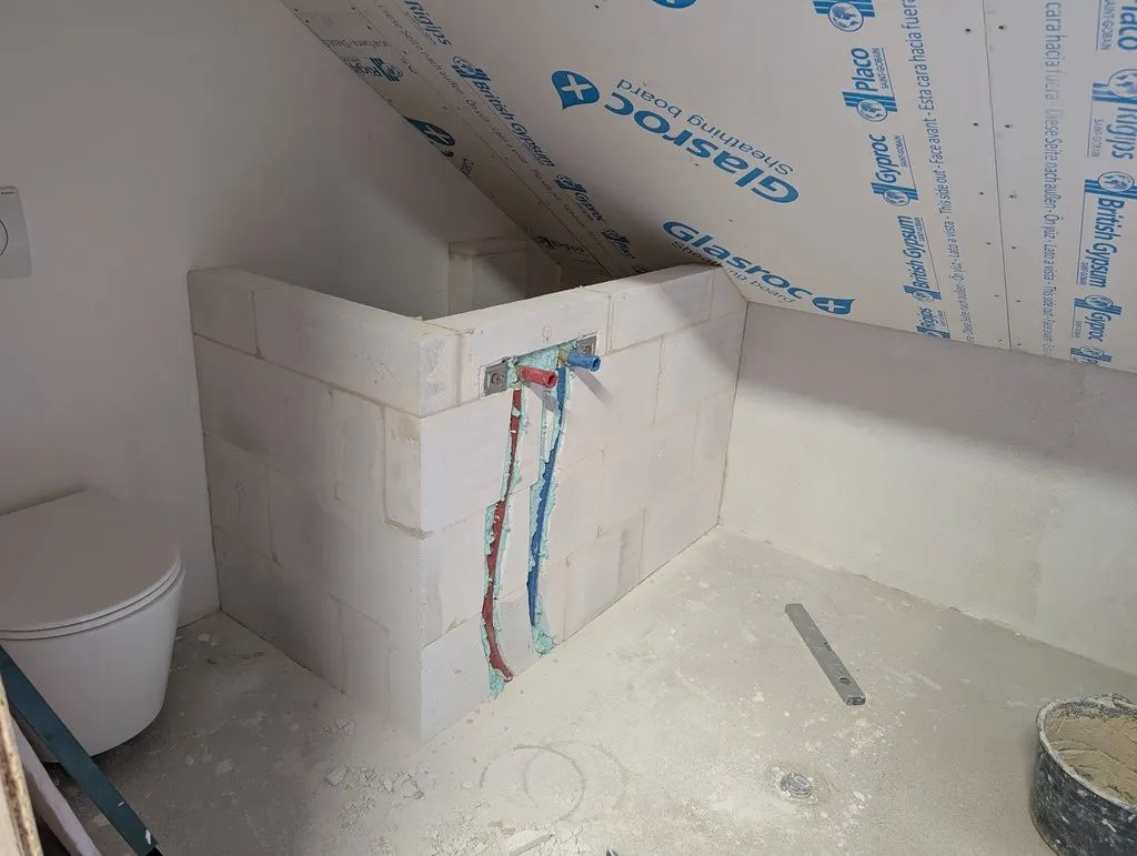
The completed "pony wall" that holds the hot and cold water lines for the bathtub and walls of the plumbing in the back.
Bathroom drywall and cement board
The bathroom interior is finished with a combination of cement board and water-resistant drywall ("Glasroc X" and "Aquaroc", respectively, both manufactured by Saint Gobain). We used cementboard in the heavily-exposed areas (e.g. around the bath and sink) and drywall in the ceiling and less-exposed walls.
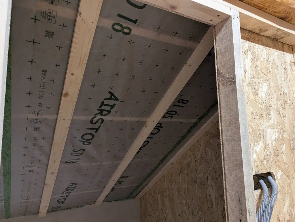
These wooden slats will provide a fastening surface for the drywall boards.
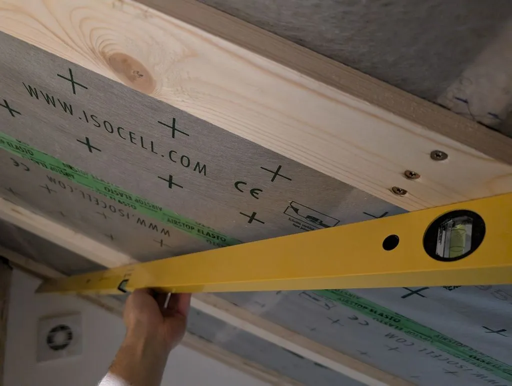
Using a straight edge to ensure the slats for the drywall are planar.
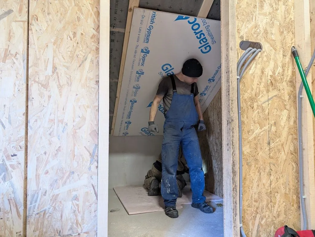
Holding up the first board of ceiling drywall with my back while my cousin Anže, who once again came to rescue, attaches the board below.
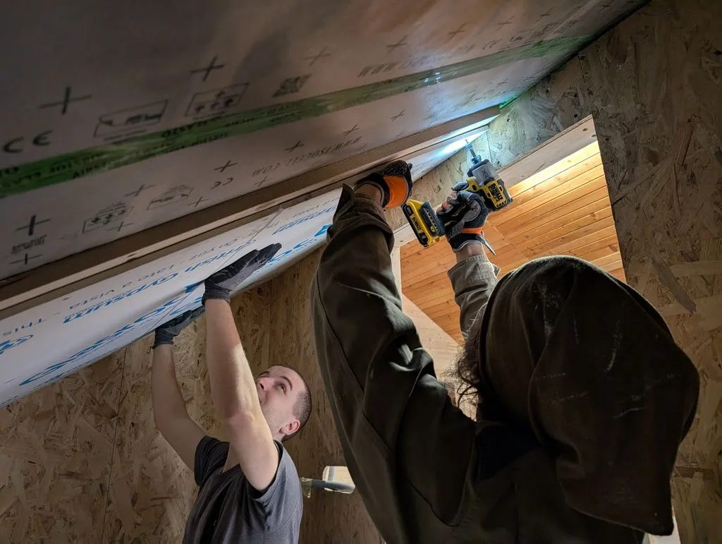
Anže attaching the ceiling drywall while I hold the board in place.
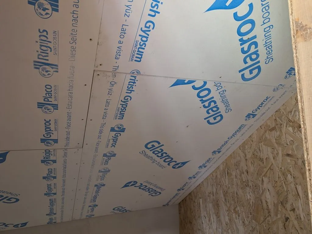
Completed ceiling drywall installation.
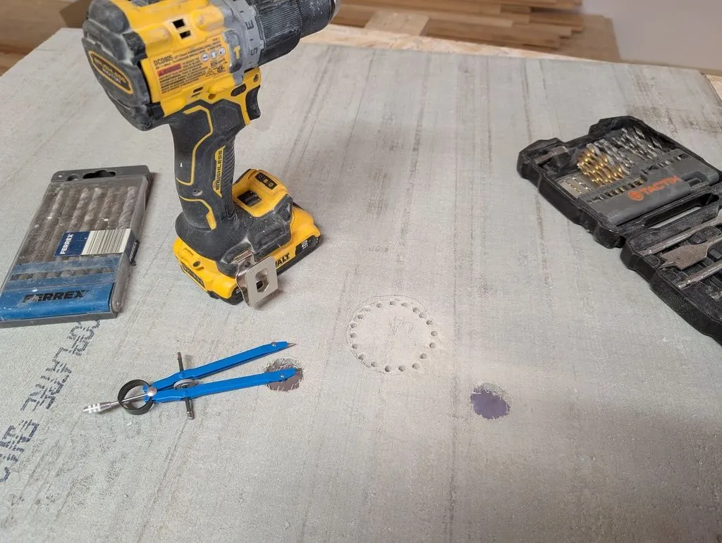
Marking and drilling holes in the cement board to fit over plumbing lines. True to its name, the cement board is difficult to work and will immediatly dull a conventional drywall hole saw. I instead drilled out the circumference of large holes with a masonry bit, then punched out the hole.
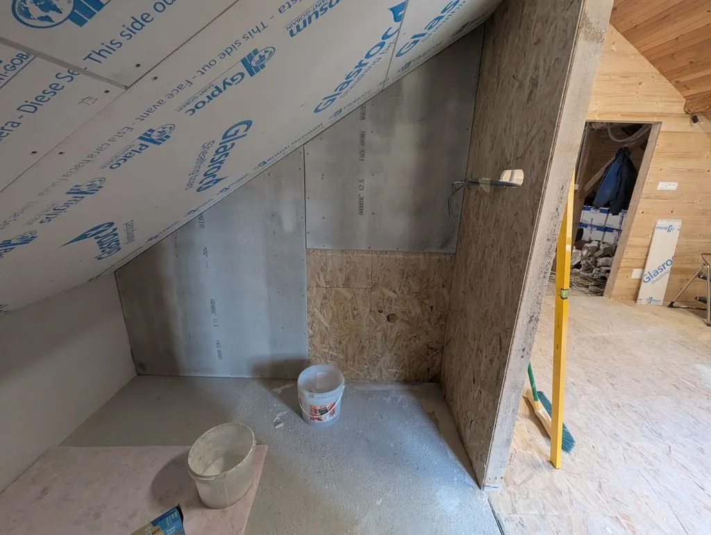
Installing the first pieces of cement board (we used cement board in the water-exposed areas near the bathtub and sink).
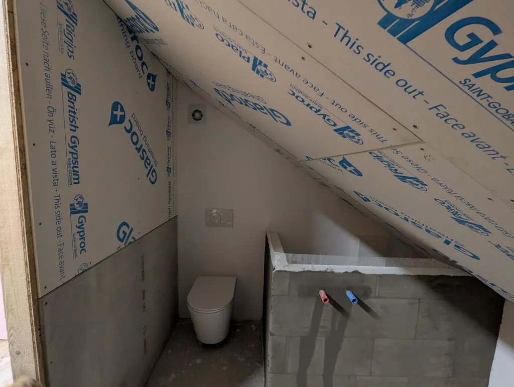
The completed drywall/cement board installation.
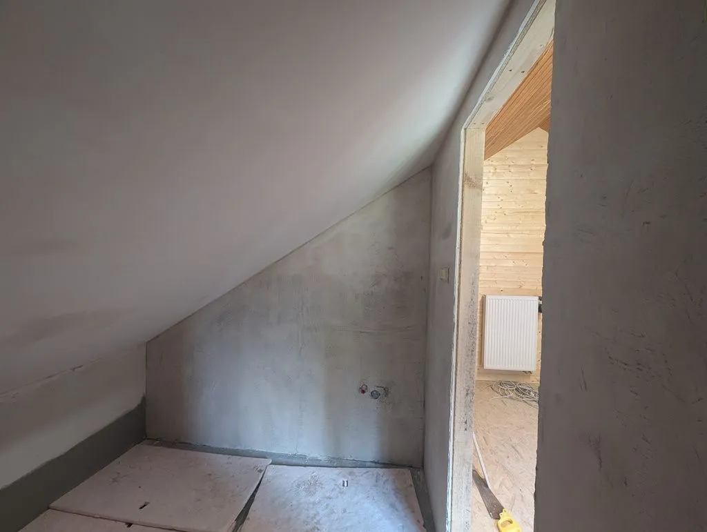
The completed interior surfaces after taping and finishing. We finished the drywall with standard gypsum-based drywall compound and finished the cement board with a lime-cement render. The ceiling and some of the walls will later be painted, and some tiled.
Waterproofing the bathroom
We waterproofed the bathroom with an acrylic, brushed-on waterproofing compound manufactured by Ceresit. The surfaces are first impregnated with a primer (CT17), then finished with two brushed-on layers of waterproofing compound (CL51), applied in perpendicular directions.
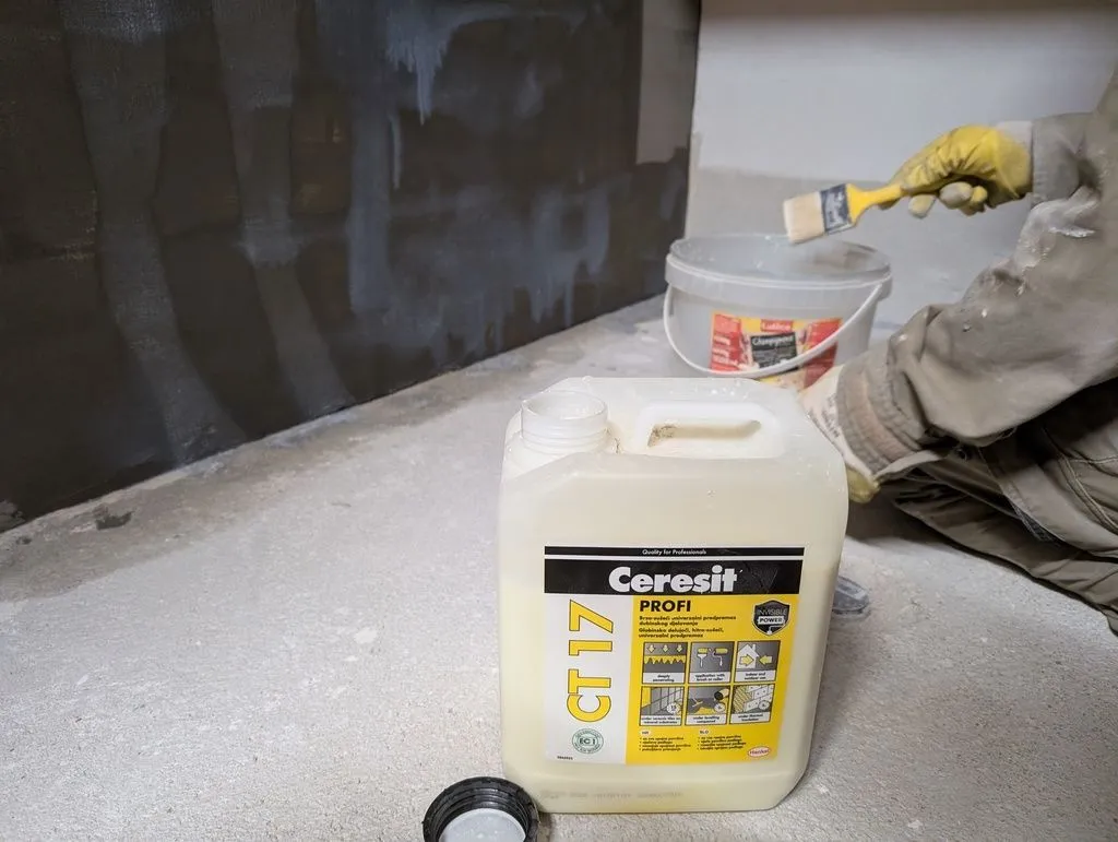
We first applied a coat of primer to all waterproofed surfaces to ensure a better bond of the waterproofing compound.
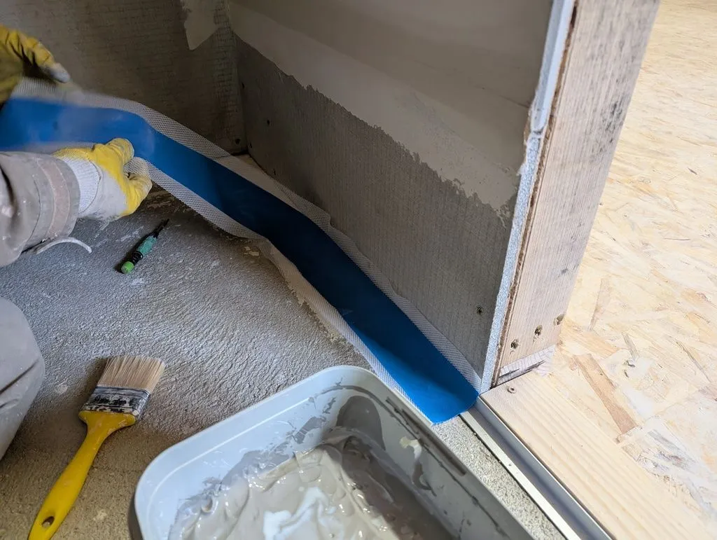
An elastic waterproofing tape is applied over all corners; the waterproofing compound is then applied over the tape.
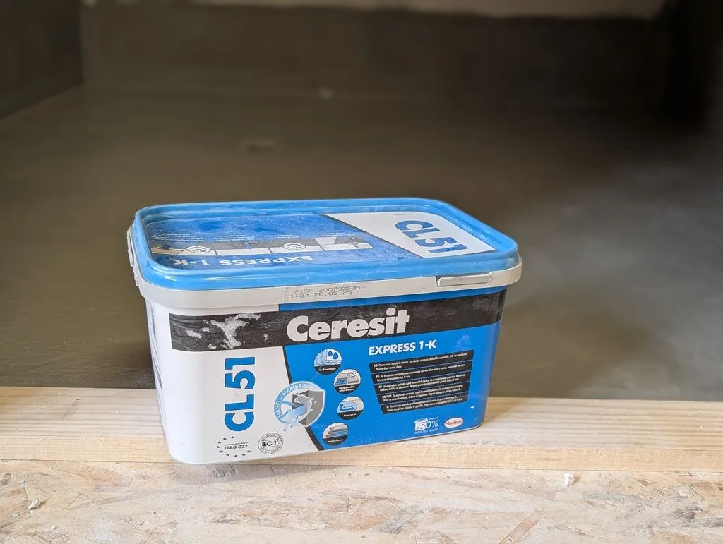
CL51, a brushed-on acrylic waterproofing compound.
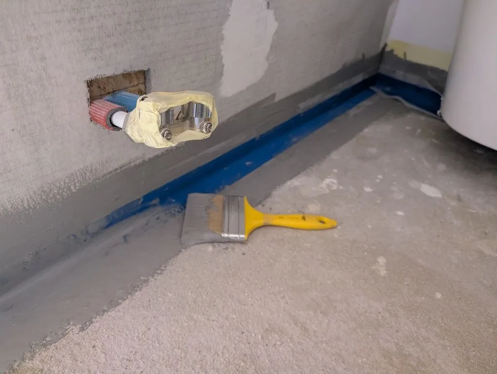
Beginning the waterproofing. The waterproofing compound is applied by brush in two layers. The second layer is applied, with brush strokes perpendicular to the first layer, a few hours after the first layer.
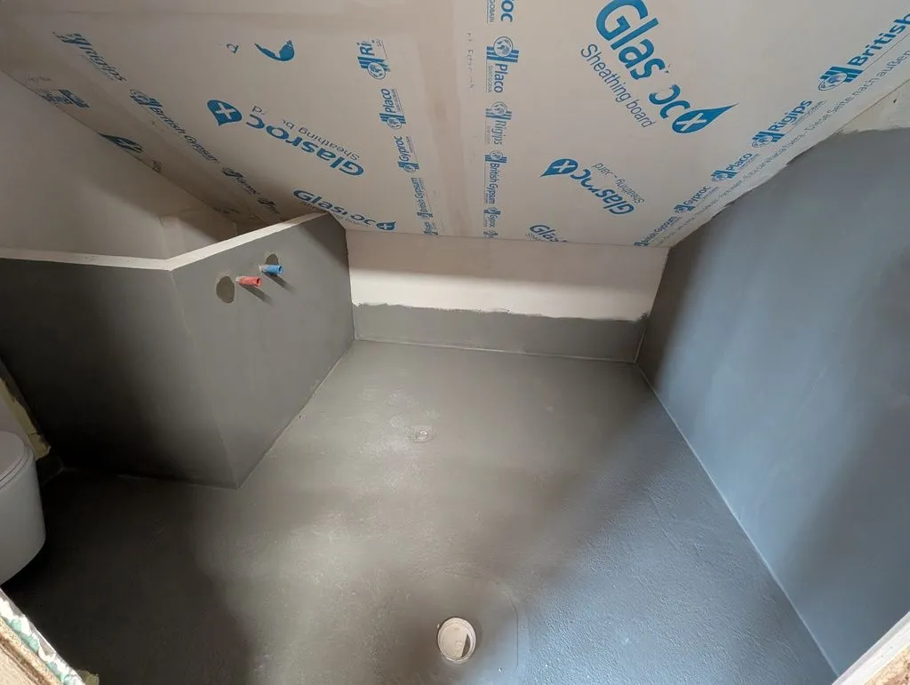
The waterproofed bathroom. We covered the entire floor and the walls around the wet areas by the bathroom and sink.
Bathroom lights and ventilation fan
We reused the bathroom lights from an old apartment!
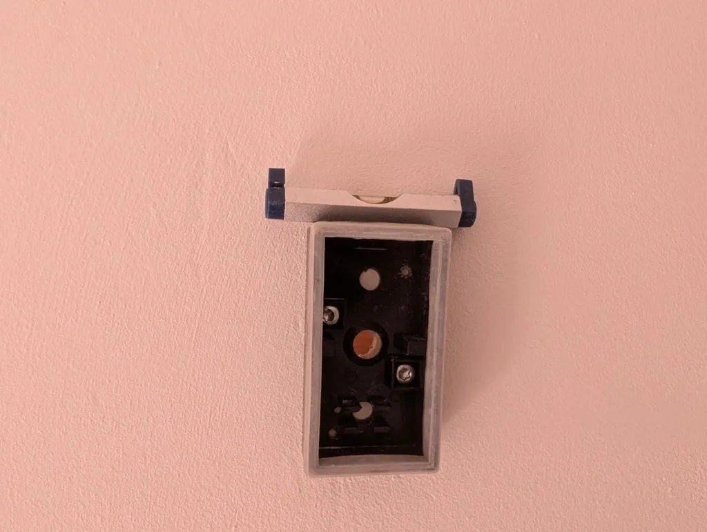
Checking the light box for level.
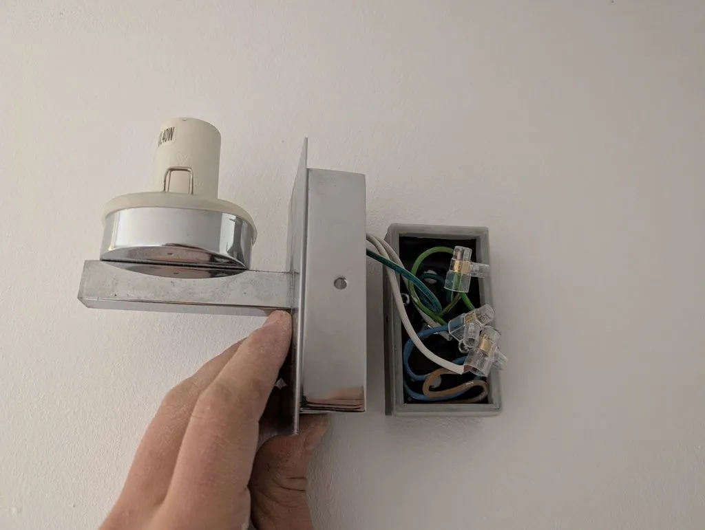
The wired up light box.
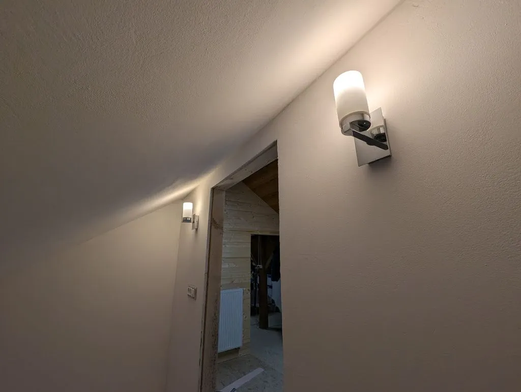
The completed bathroom lights.
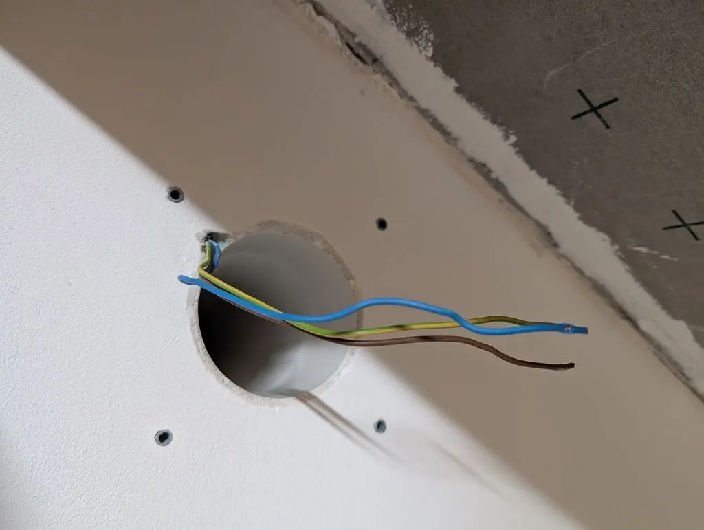
Supply conductors and ducting for the ventilation fan. The four holes in the wall are wall anchors for the ventilation's mounting frame.
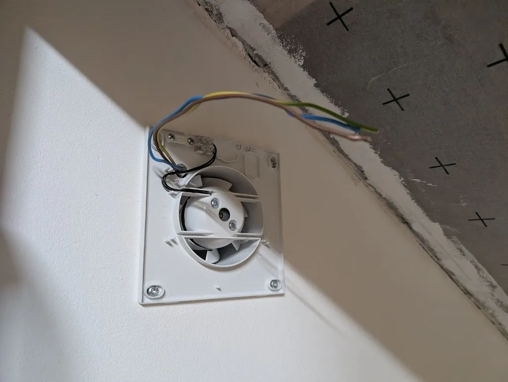
The fan's mounting frame attached, with wiring routed in.
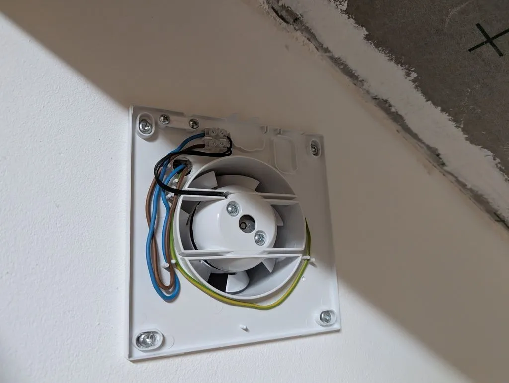
The wired-up bathroom fan.
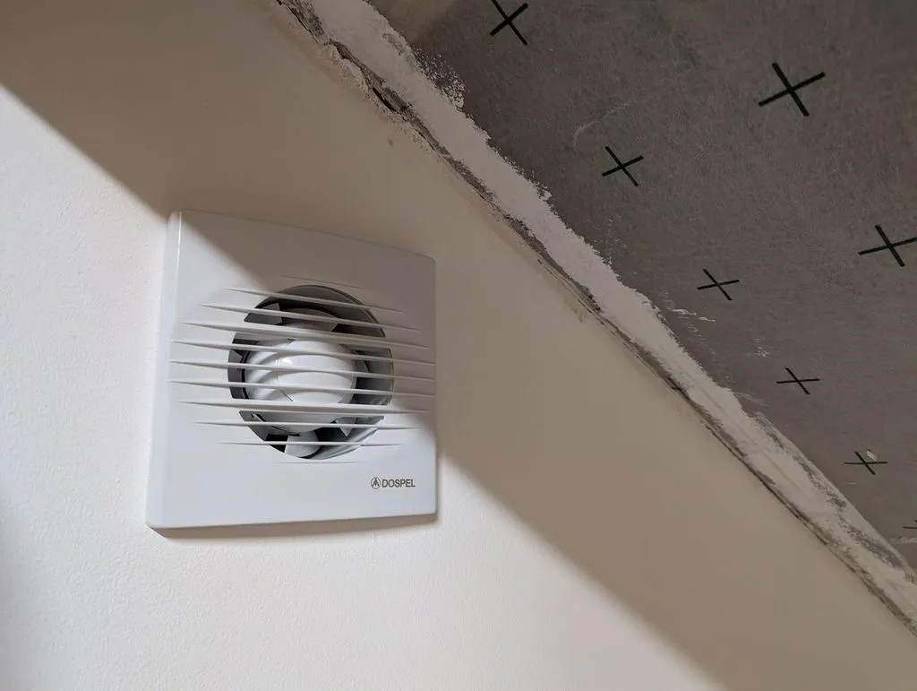
The completed bathroom ventilation fan.
Interlude: bathroom cabinets
We went for the easy route and purchased a stock bathroom cabinets instead of building the bathroom cabinets myself. However, the stock cabinet needed a bit of modification to fit under the sloped bathroom ceiling.
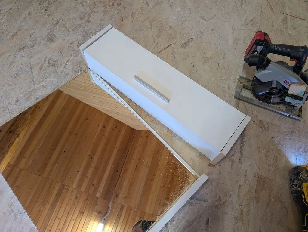
I separated the mirror from the shelf, because otherwise the assembly was too wide to install under the sloped bathroom ceiling.
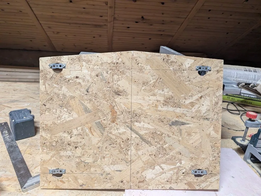
This OSB board will hold the mirror. The clips at the four corners will slip onto mounting brackets on the wall.
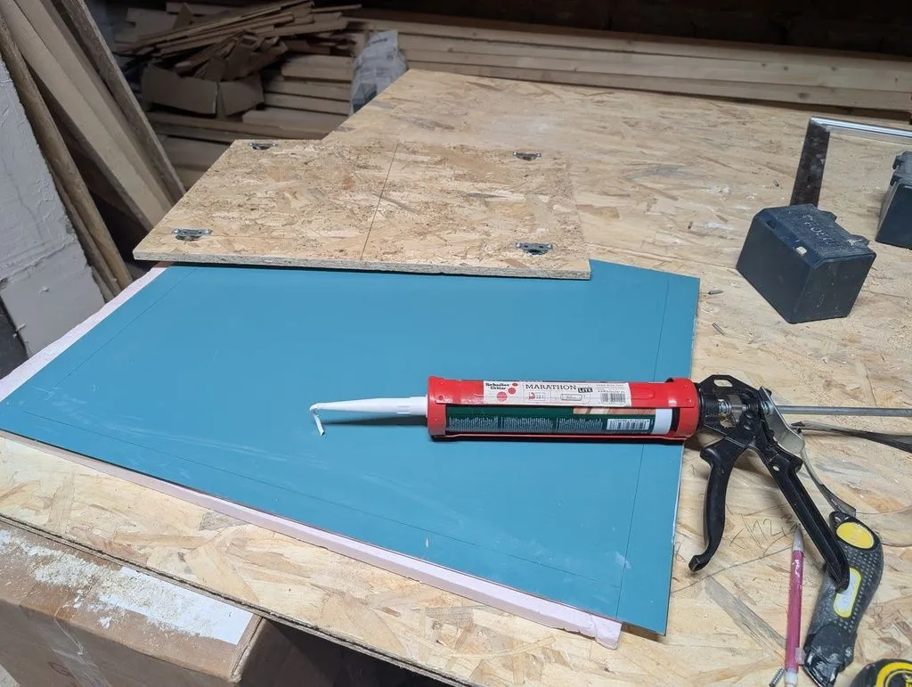
Attaching the mirror to the OSB mounting board with construction adhesive.
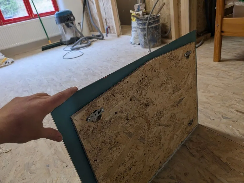
The mirror attached to the mounting board.
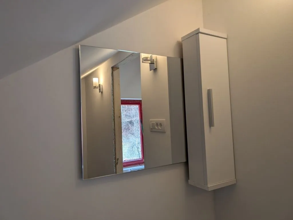
The installed mirror and cabinet. A cap piece holding an LED strip light will later go over the top of the mirror.
Bathtub enclosure walls
The enclosure holding the bathtub is built out of aerated concrete, with a large flat shelf area (e.g. for towels, soap, shampoo, etc.) in the "dead area" under the slope of the roof.
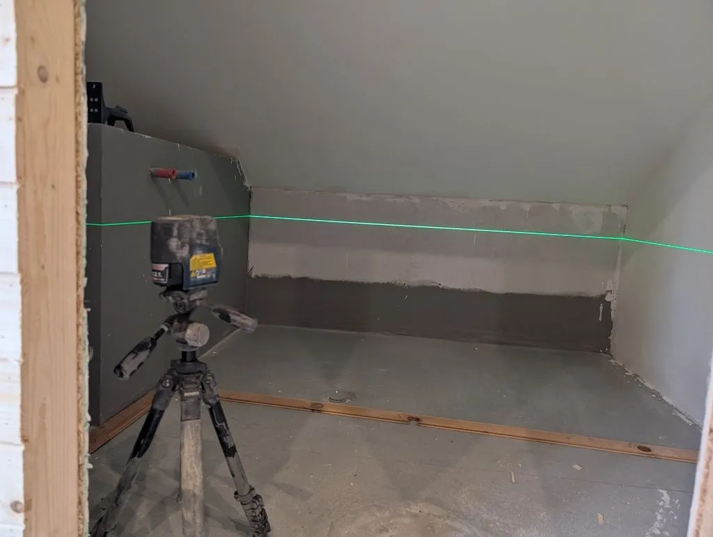
Using a laser level to mark the final height of the bathtub walls.
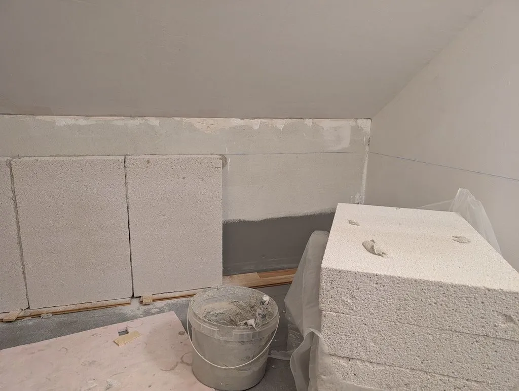
The bathtub enclosure is made of aerated concrete blocks. This is the first row of the flat area behind the bathtub.
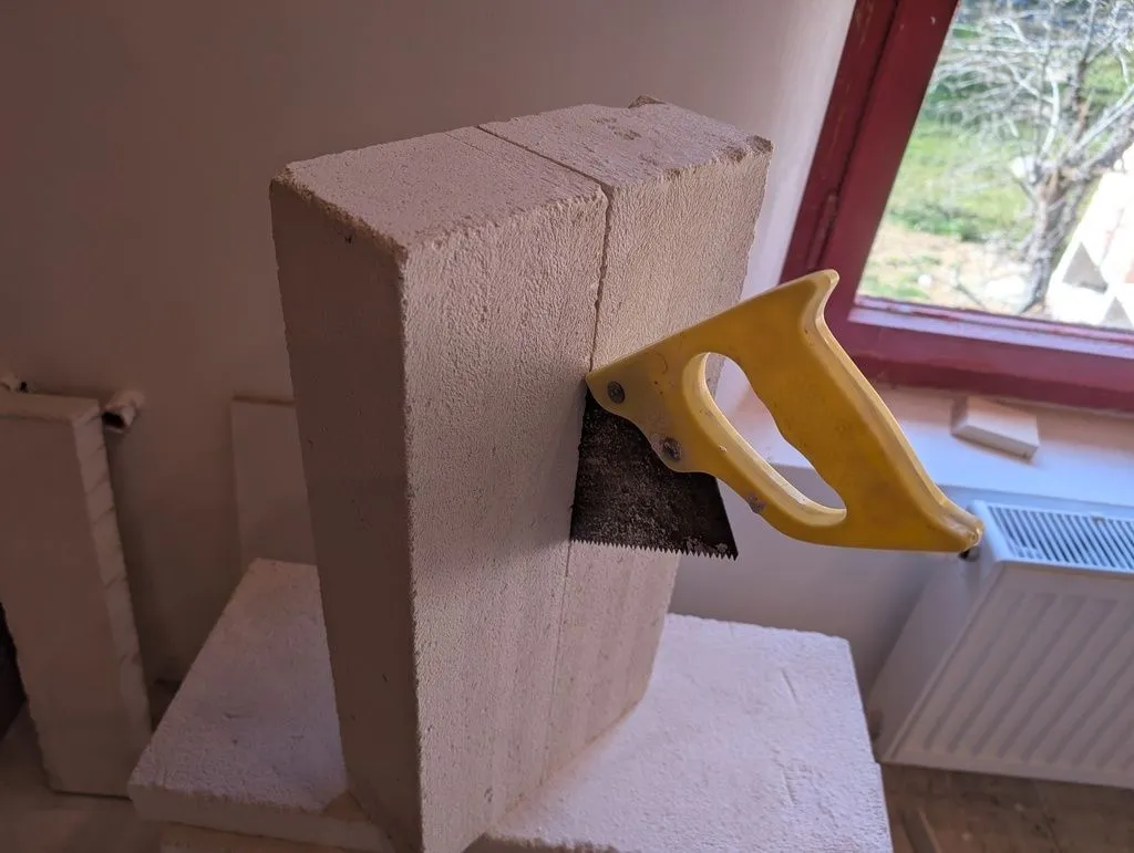
The aerated concrete blocks are cut without too much difficulty using hand saw (there a specialized saws for this purpose with large proprietary teeth, but a regular wood saw worked fine for me on this small-scale job).
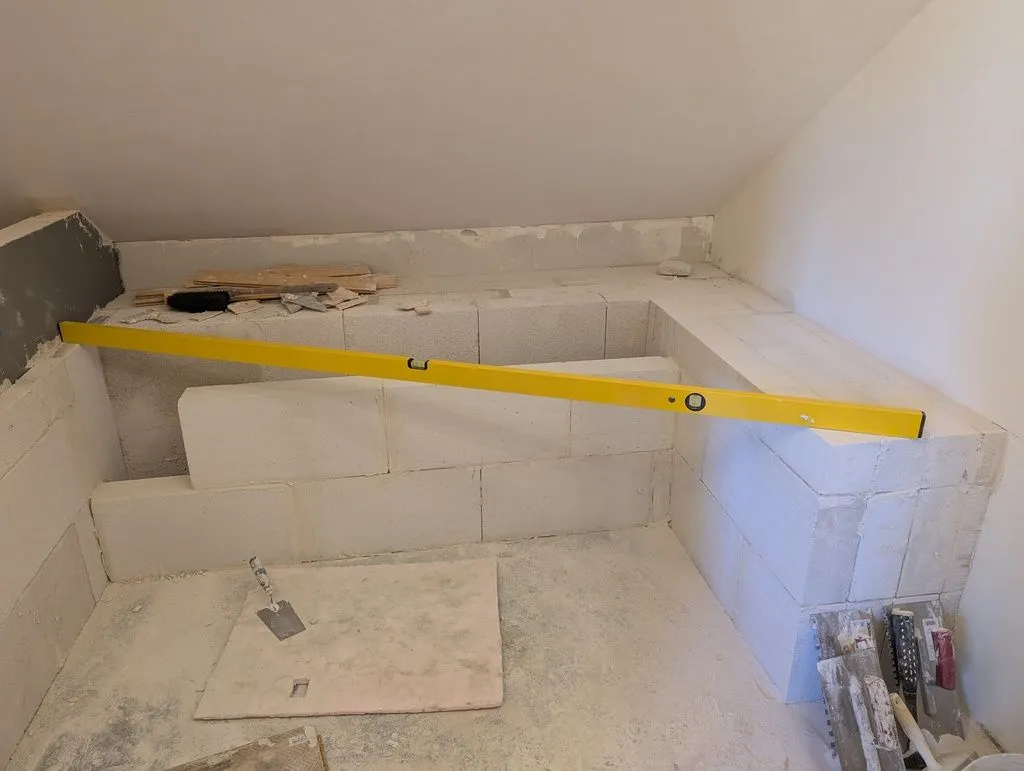
Checking the walls for level. The wall in the foreground will support the bathtub; the area in the back will be a flat space on which to place towels, soap, etc.
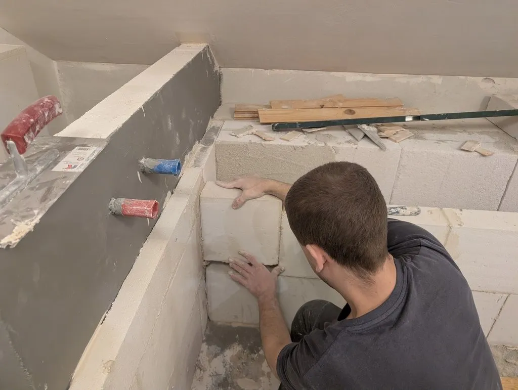
Setting in place the final block of far bathtub wall.
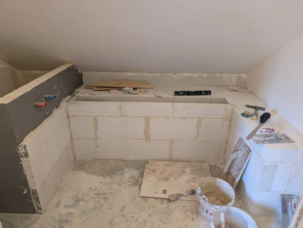
The (nearly complete) bathtub enclosure. I would later add the front wall and fill in the small trench in the flat area in the back.
Bathtub screed
We formed the final few centimeters of the bathtub enclosure with cementitious screed, which would form a nice firm surface for tile and could be easily shaped to get proper slope towards the bathtub in all directions.
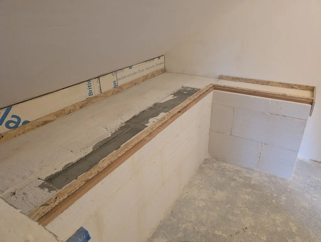
Small strips of OSB serve as the formwork for the screed.
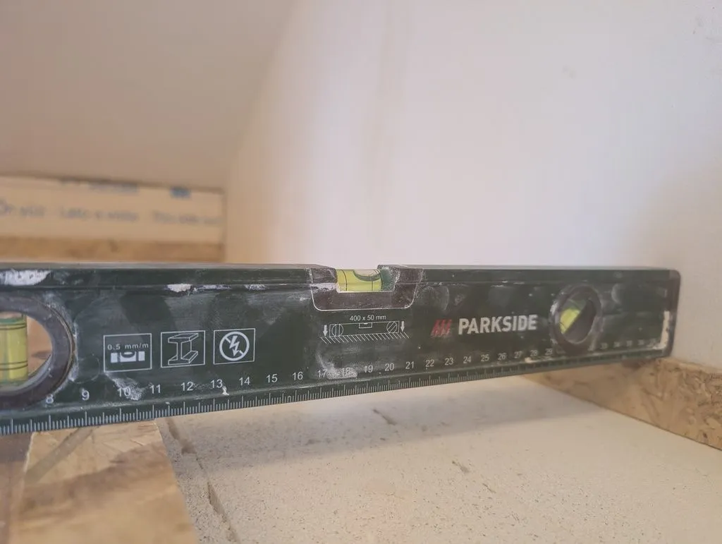
The formwork is intentionally taller in the back to create a slope that will make water run into the bathtub.
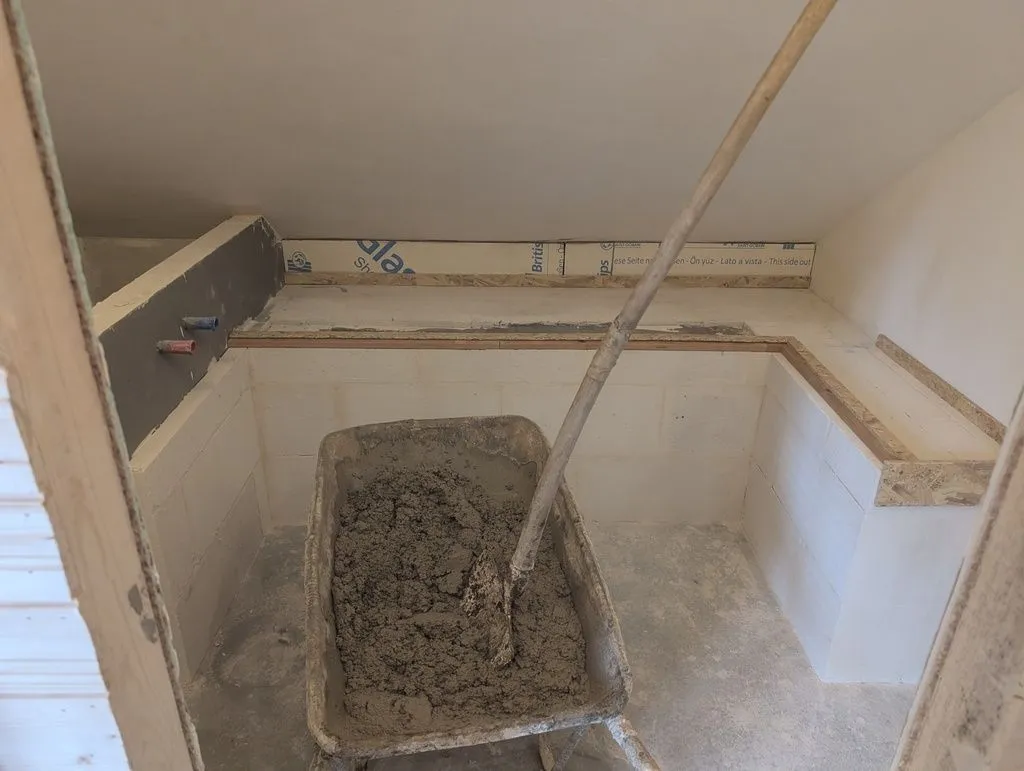
Screed mixed and ready for laying.
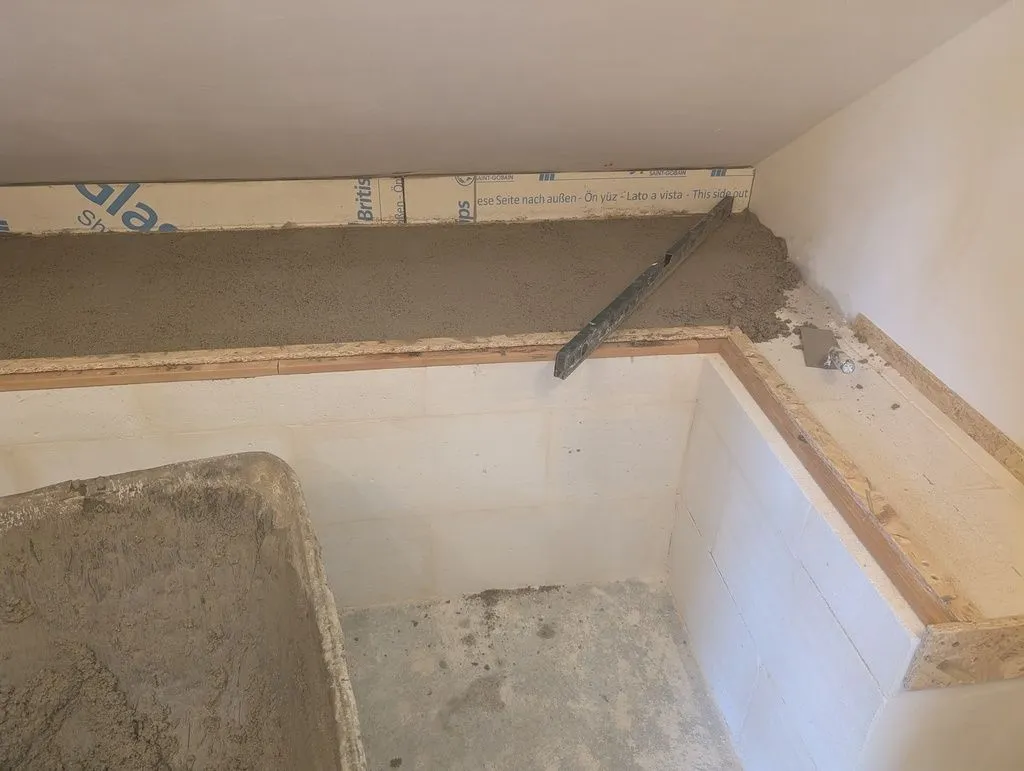
Striking off the screed using a level as a straightedge.
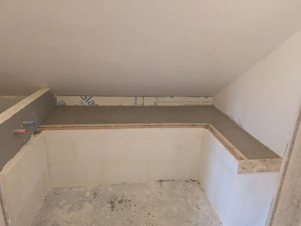
The completed screed, ready to receive tiles.
Bathtub installation
The bathtub is a standard acrylic tub, placed on the enclosure built in the previous section. One detail worth mentioning: we filled the gaps between the bathtub and the enclosure walls with a combination of XPS and spray foam. This both insulates the bathtub (so it holds heat for longer) and mechanically supports the bathtub, so it won't flex on the inside if you push it or stand on it.
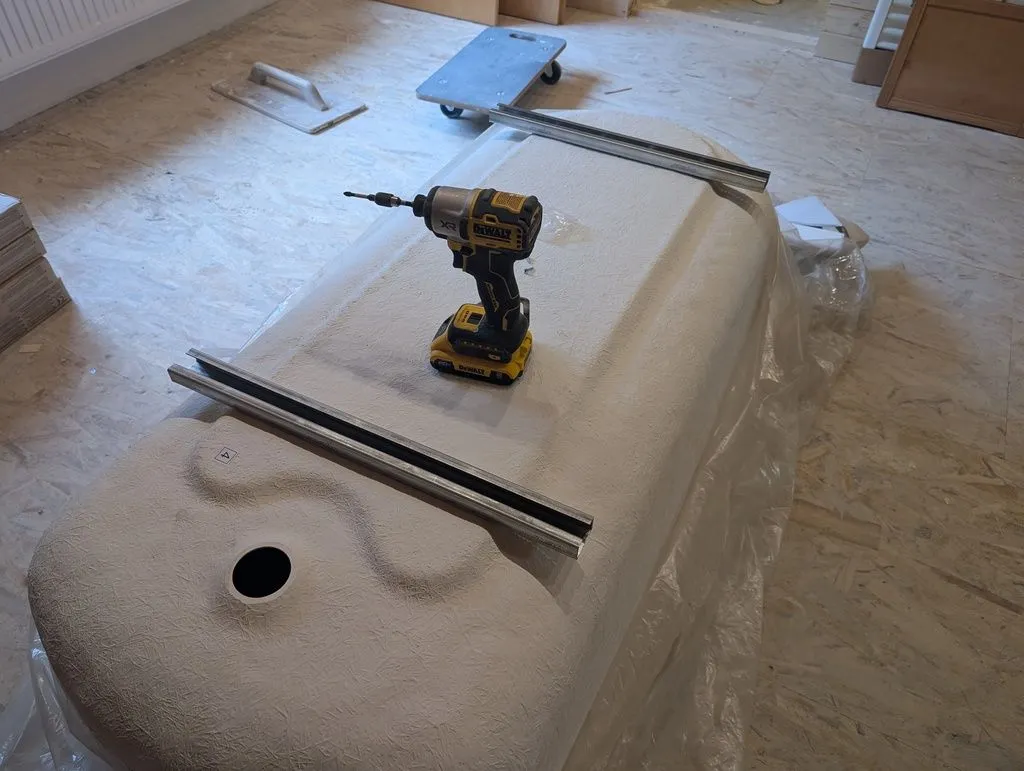
Attaching the legs to the bathtub.
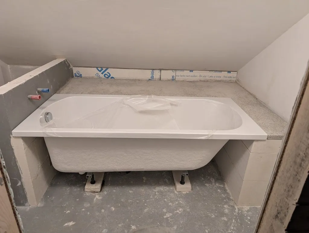
Test-fitting the bathtub. The legs are adjustable, making it easy to level the bathtub, but they were too short, so the bathtub rests on aerated concrete block (and is additionally supported around its edge by the wall enclosure).
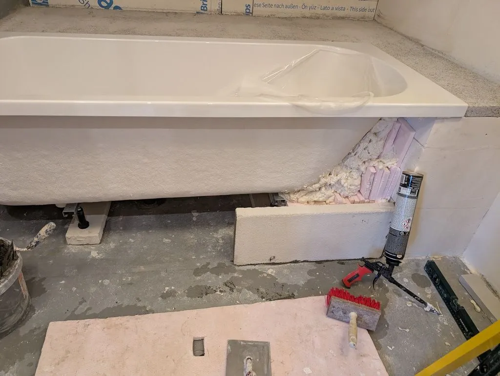
Insulating the area between the bathtub and enclosure walls with XPS and spray foam. This supports the bathtub mechanically and retains heat in the water.
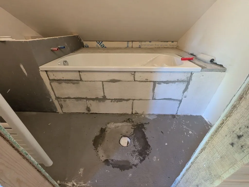
The completed front wall, again build of aerated concrete block.
Self-leveling compound (pre-tiling)
We poured self-leveling compound over the bathroom floor before tiling to fill in any gaps and irregularities in the screed below.
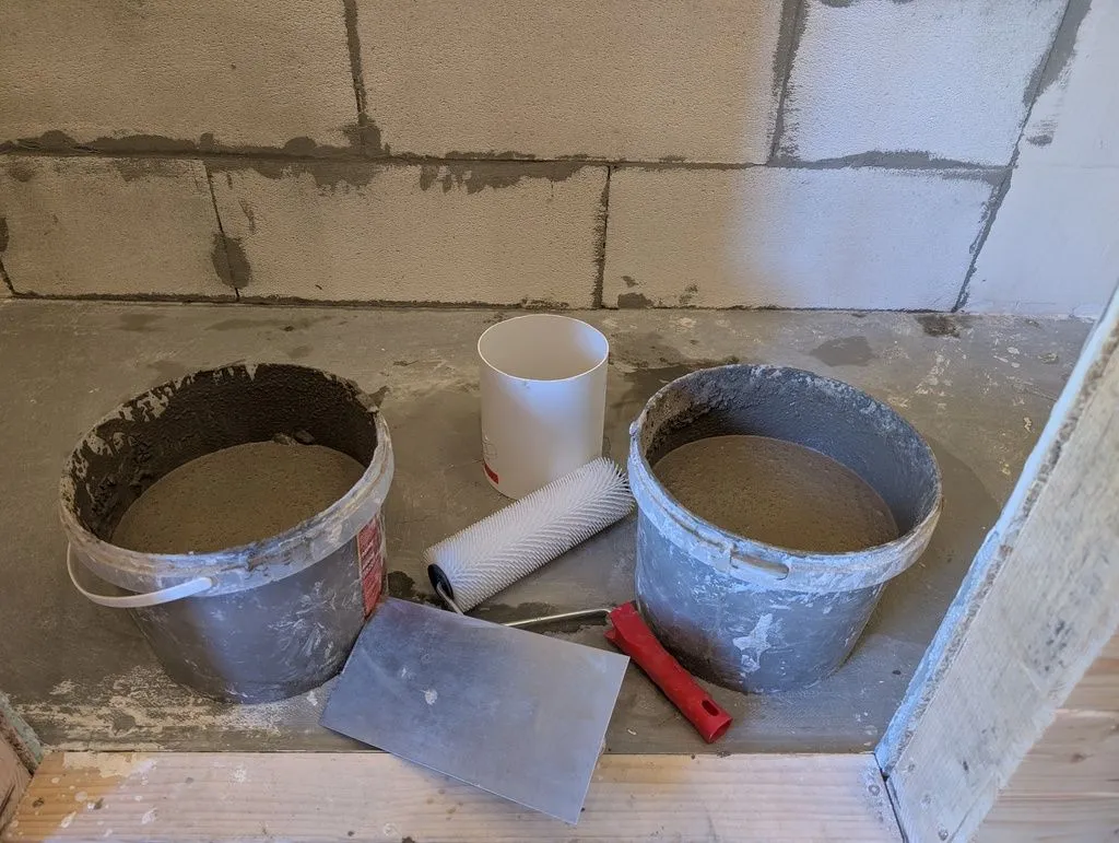
The self-leveling compound is cementitious/mineral-based and bonds nicely to the cementitious screed floor. You mix the material you'll need in buckets, then pour it all at once.
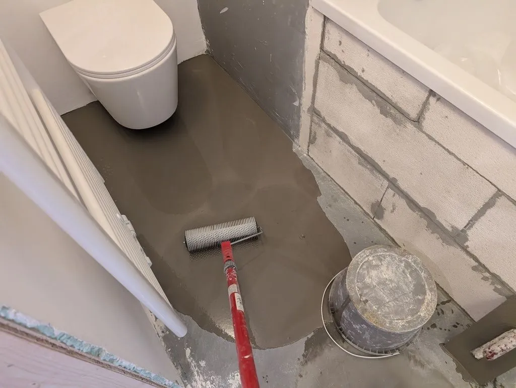
Rolling the compound with a bristly roller to work out air bubbles.
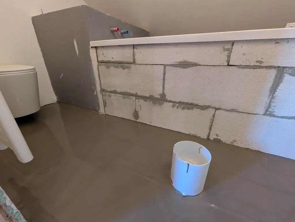
The poured self-leveling compound, which produces a smooth, level, planar surface.
Tiling the bathroom
We used a matte white 300 mm x 600 mm ceramic tile for the walls and bathtub surfaces and a textured 600 mm x 600 mm non-slip granite tile for the floor—the large format tiles make the installation quick. The dimensions of the bathtub and walls are intentionally designed to align with the modular 300 mm tile grid, minimizing cutting. We first tiled the floors, then the walls and bathtub surfaces, which avoids grout seam around the perimeter of the floor.
This was my first time tiling, and our neighbor Zdravko (an amazing man, but those are stories for another time) came to show me how the process works and lent me his tile saw for the duration of the job. We did the first part of the floor together, and then Martin and I did the rest of the job ourselves.
Tiling the floor
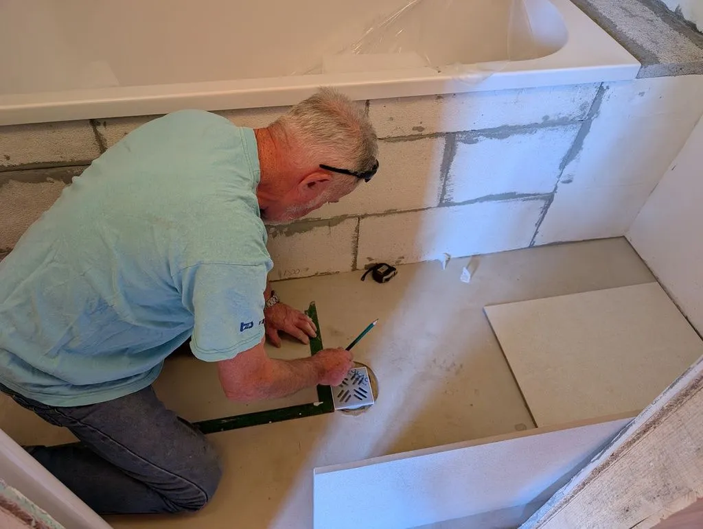
Zdravko taking measurements needed to fit the tiles around the floor drain.
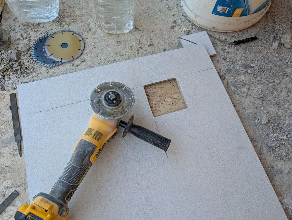
The opening for the hole drain, cut with a diamond-tipped cutting disk on the angle grinder. The floor tiles are granite and quite a challenge to cut (the ceramic wall tiles were softer and much easier to cut).
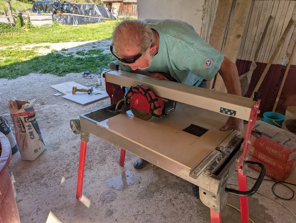
Zdravko showing me how to cut tiles on the tile saw, which he lent me for the duration of the job. This was a wonderful tool to have—it is both precise and continuously wets the tiles with a jet of water, eliminating dust.
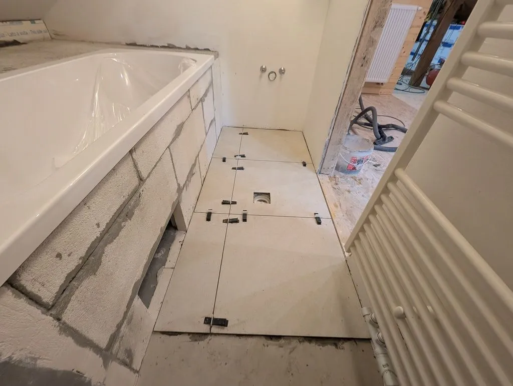
The first phase of the floor tiling complete. We did this in two phases—the long narrow geometry of the bathroom floor makes it difficult to do in a single phase without boxing yourself in.
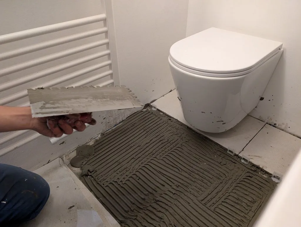
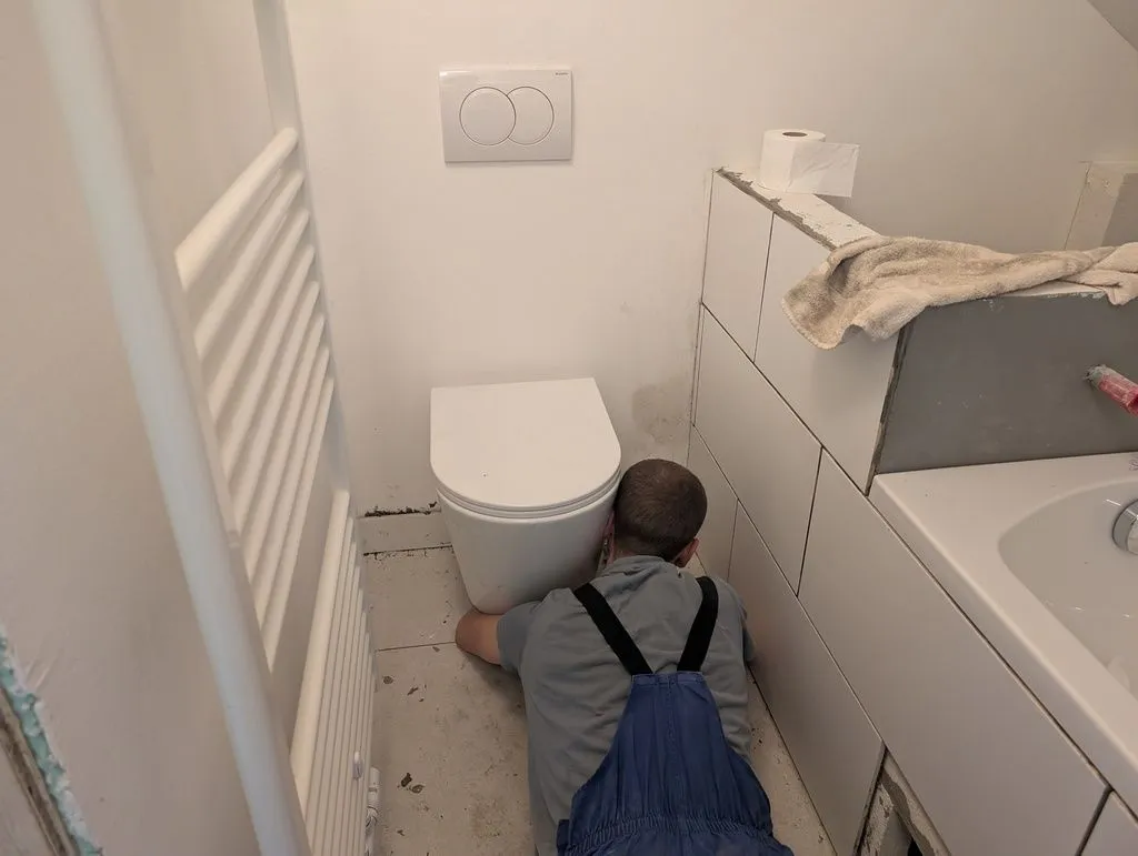
Completing the second phase of floor tiling—the suspended toilet makes it easy to tile under the toilet, as opposed to cutting tile to fit around a traditional floor-draining toilet. Notice how I am inexperienced and getting thinset everywhere—much more of that to come!
Tiling the bathtub area
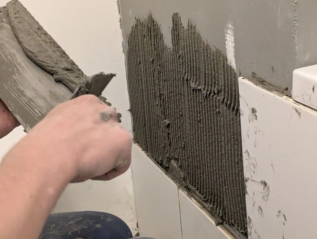
Applying tile adhesive to the bathtub walls. A notched trowel is used to create the neat line pattern—this makes for a better bond when the tile is pressed into the adhesive, and makes it easy to spread a consistent thickness adhesive.
Applying skirting/baseboard tile around the perimeter of the bathroom floor, including under the toilet.
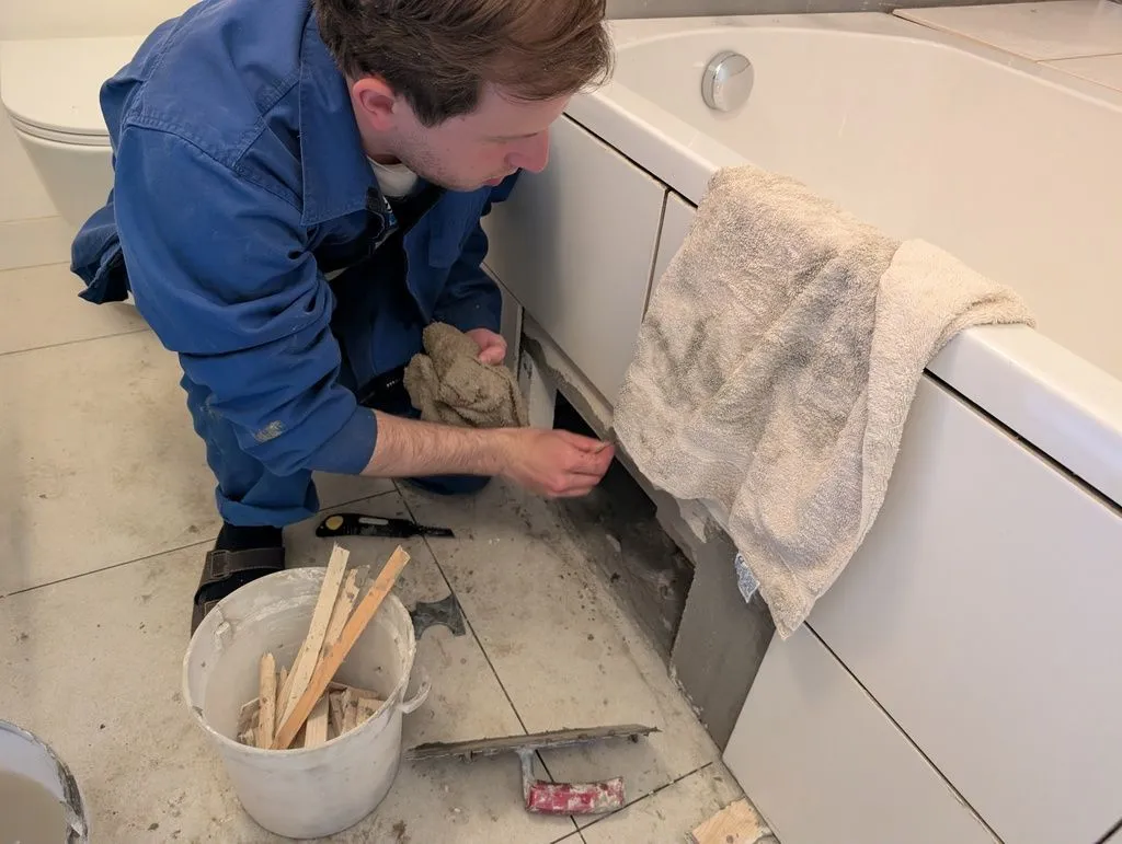
Martin did a wonderful job of cleaning up the thinset I spread everywhere with my inexperienced hands. The hole in the wall is for an access hatch for servicing the bathtub plumbing—more on this below.
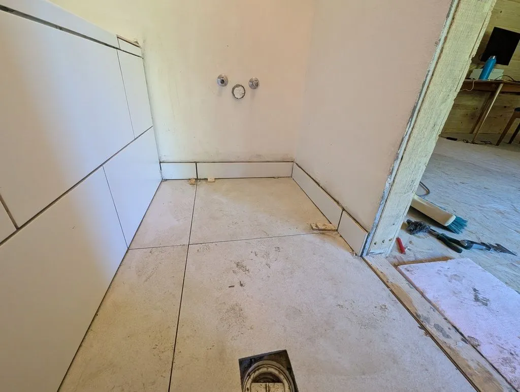
The skirting/baseboard tile complete.
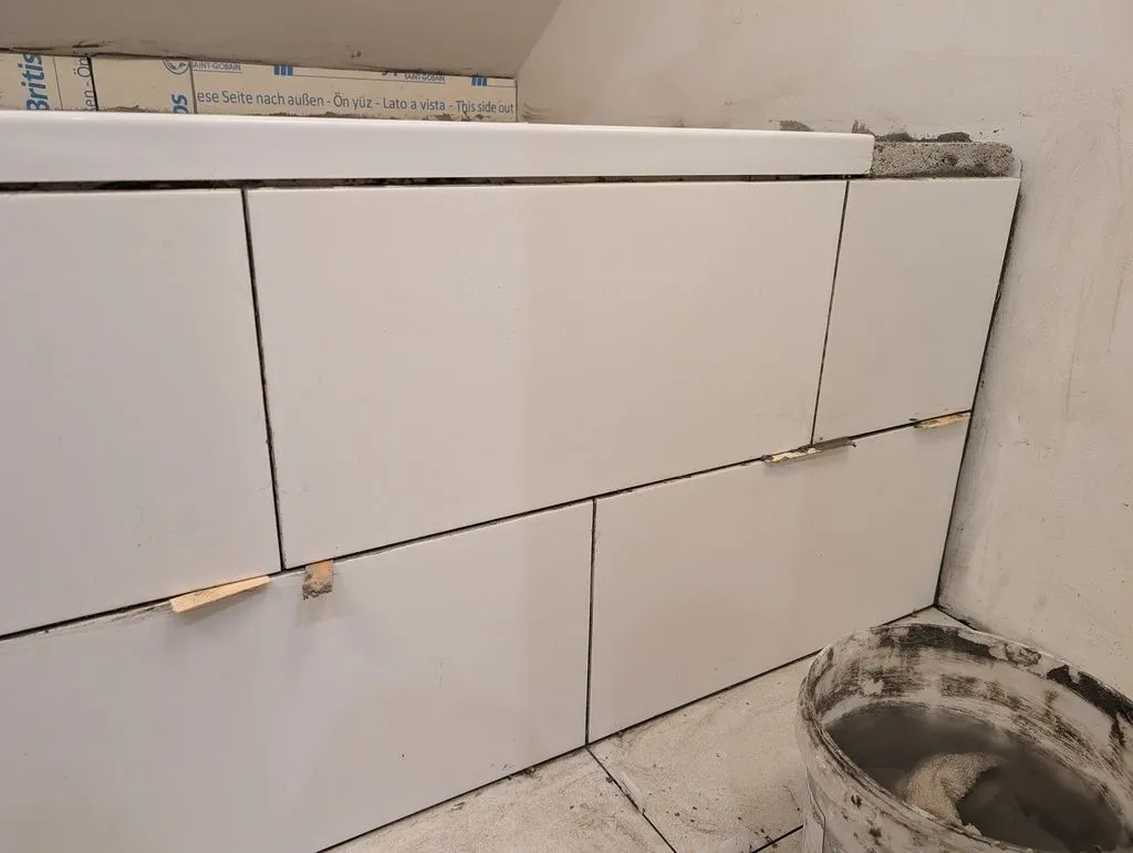
The bathtub wall complete.
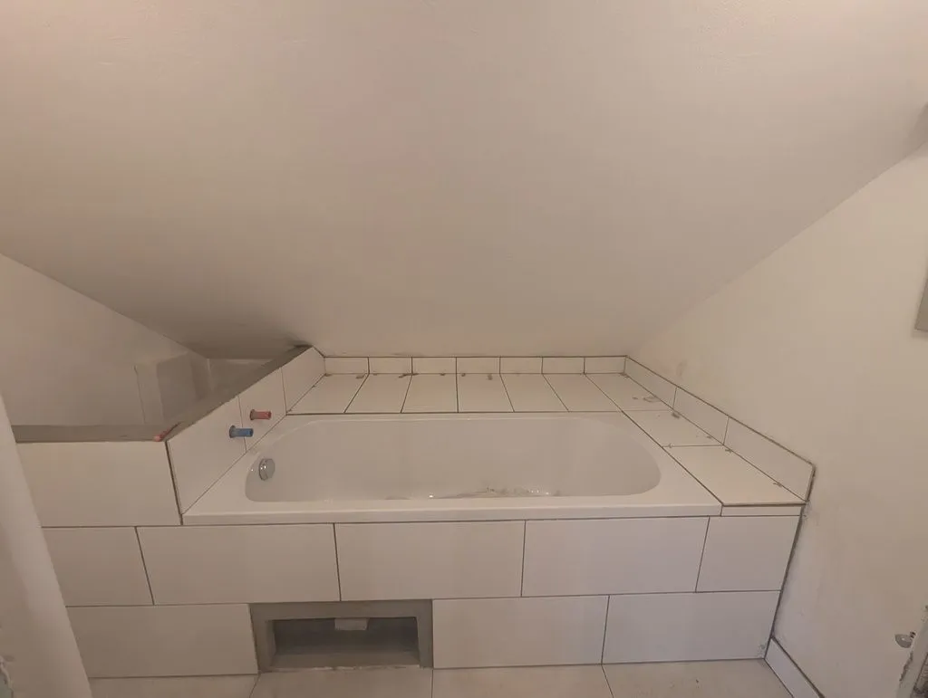
The flat area at the top of the bathtub complete. The hole at the base of the tub is for servicing the bathtub drain, and will be covered by a removable blind tile—more on this below.
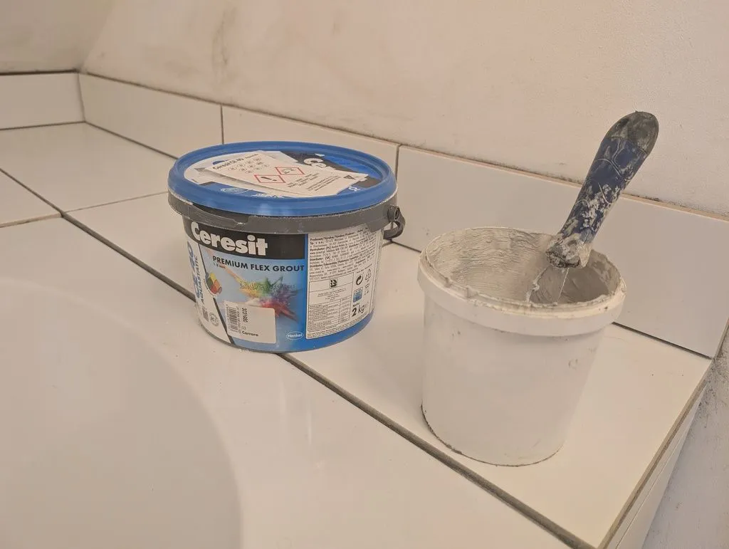
We grouted the tile with a flexible off-white CE-40 grout made by Ceresit.
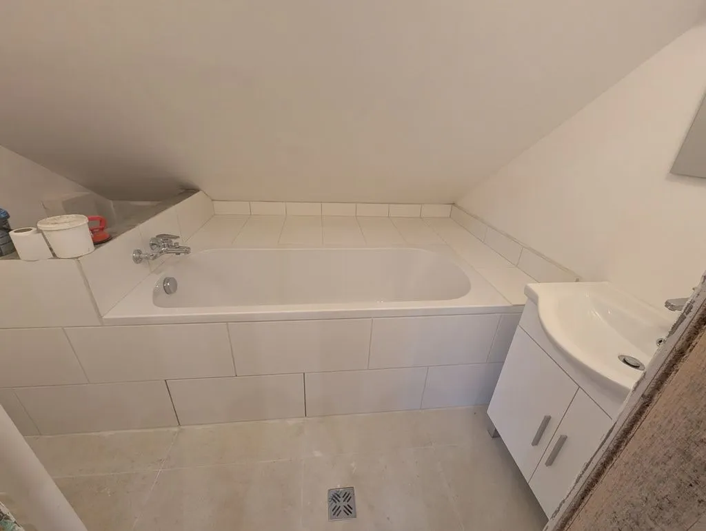
The completed tiling job. Aside from getting thinset everywhere while tiling, the job came out well enough for a first time laying tile.
Aside: access hatch for bathtub plumbing
We left an intentional hole in the wall for an access hatch which we could use to access the bathtub drain in the event of clogs or future service. The hatch will be covered by a "blind" tile attached with magnets and removed and replaced with a suction cup—I saw a similar idea once on YouTube and wanted to try it out here.
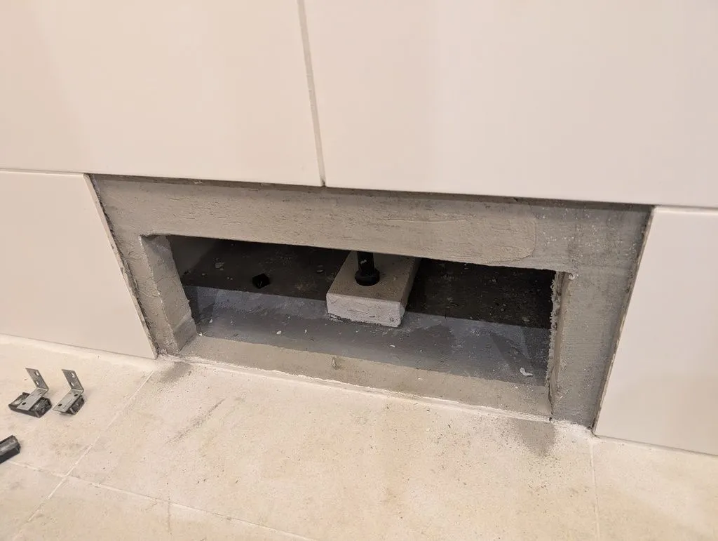
The hole in the wall for accessing the bathtub plumbing, which will be covered by a blind tile.
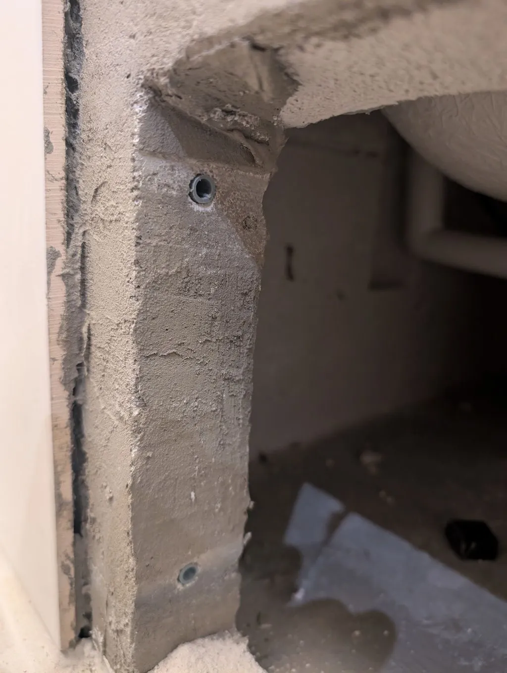
These wall anchors are for screws that will hold brackets holding the blind tile.
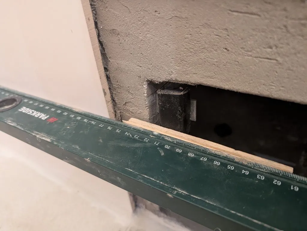
Using a straightedge with some wooden shims/gauges to judge the appropriate depth at which to attach the brackets so the blind tile will be flush with the rest of the wall.
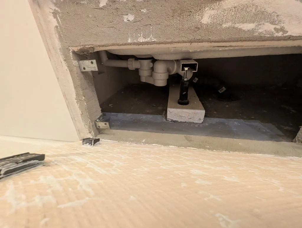
Magnets on the back of the blind tile will attach to these steel angle brackets on the wall.
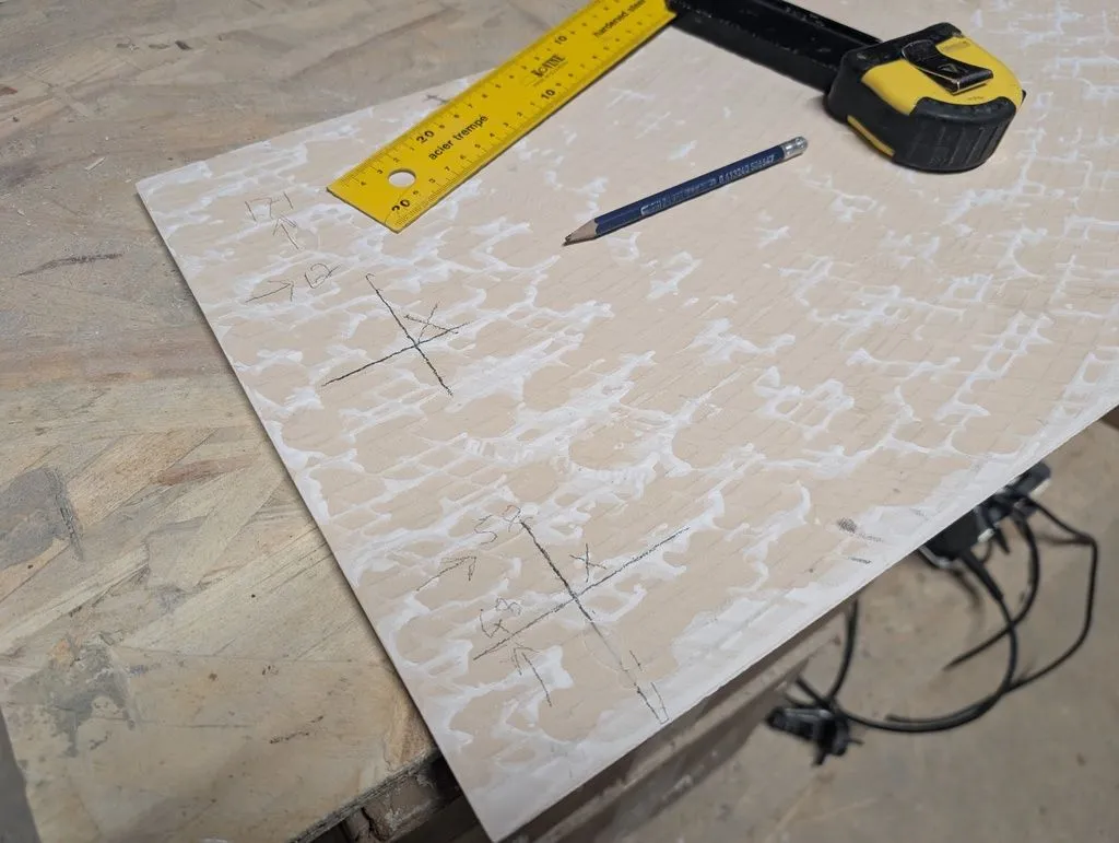
Marking the position for the magnets on the back of the blind tile.
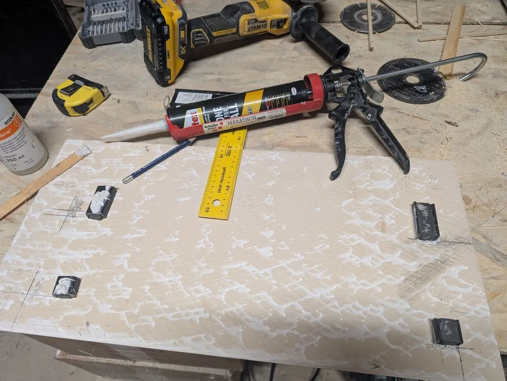
Attaching the magnets to the back of the tile with a water-resistant construction adhesive.
The blind tile is held in place magnetically...
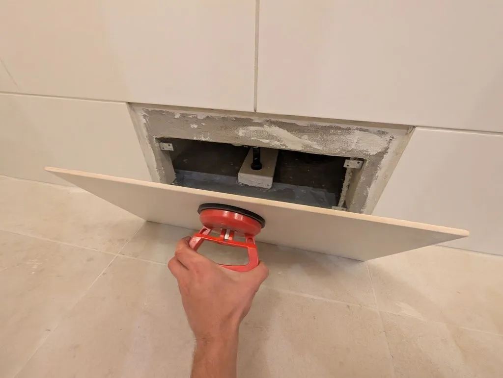
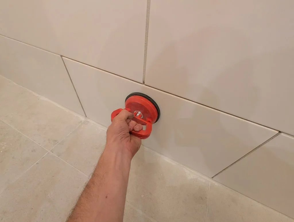
...and can be removed by suction cup.
The end result—aside from the missing grout lines, the access hatch is hardly visible if you aren't looking for it.
Wrapping up the bathroom
Miscellaneous finish work—installing the bathtub faucet, sink, shelf over the utility area, etc.
Fun aside: the entire set of bathtub fixtures (faucets and fittings for both the tub and sink) were a fun 40€ purchase off the Slovene equivalent of Craigslist or Facebook Marketplace. They are high-quality brass fixtures and would have cost many hundreds of euros if bought new (proper brass bathroom fixtures are expensive!).
Bathtub faucet
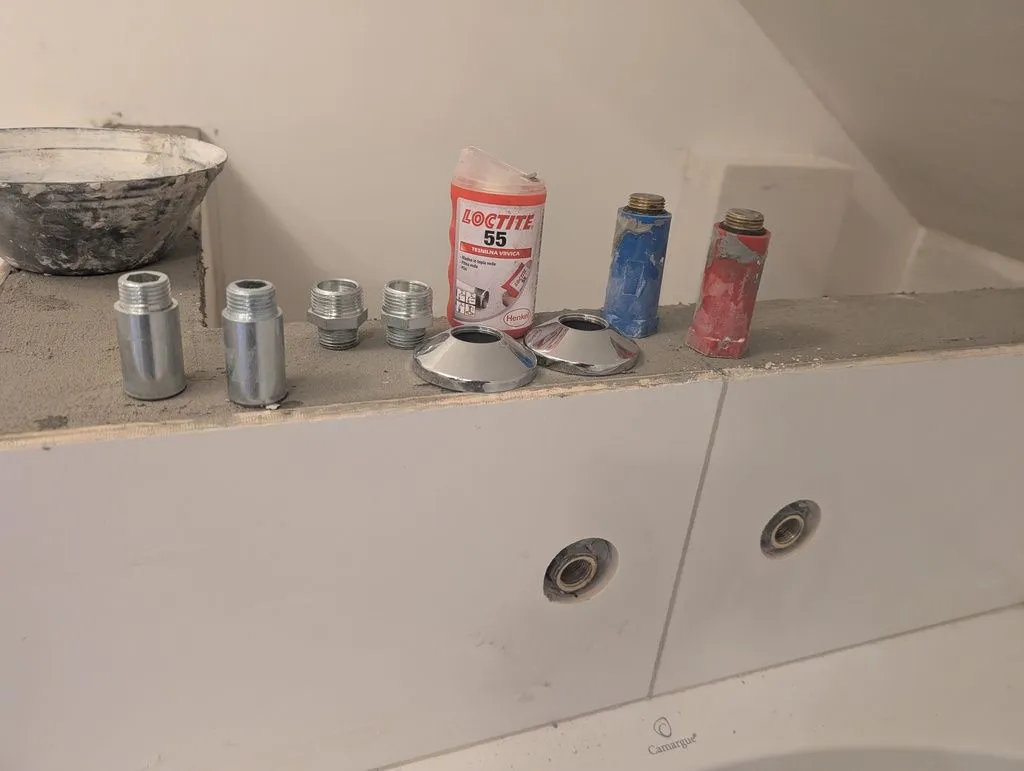
The various materials for installing the bathtub faucet (fittings, escutcheons, sealing thread, the old temporary plugs).
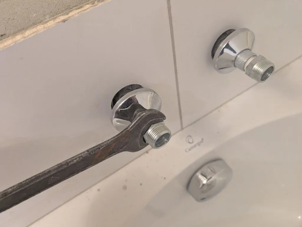
Tightening on the female-to-male fittings for the bathtub faucet.
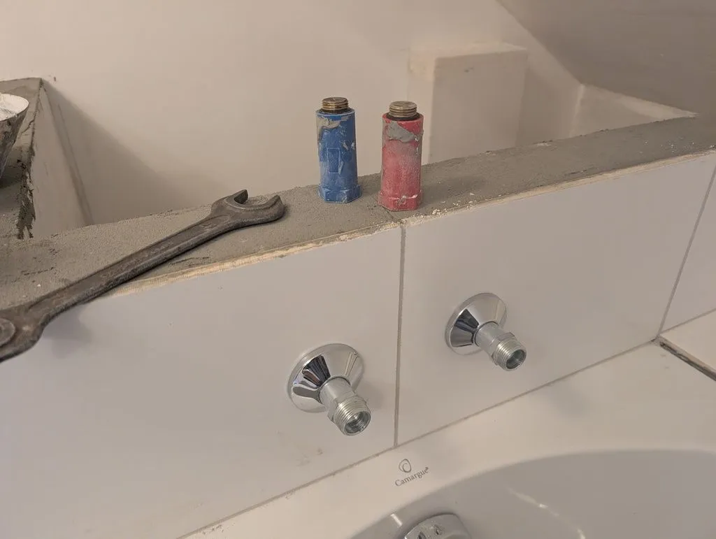
The installed fittings. The fittings intentionally project out of the wall so the water from the faucet will comfortably reach over the lip of the bathtub..
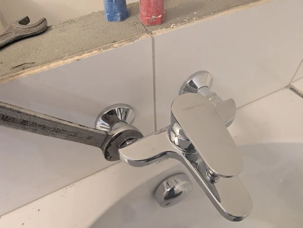
Installing the bathtub faucet.
Sink
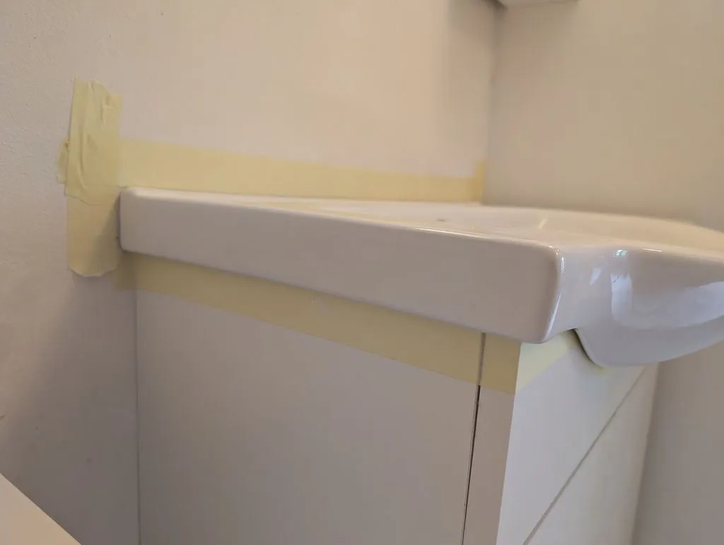
Test-fitting the sink before installing. The masking tape protects the area around the sink from the silicone sealant used to attach the sink to the base cabinet.
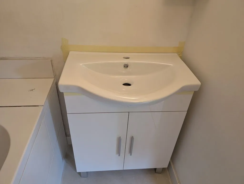
The installed sink.
Shelf over the utility area
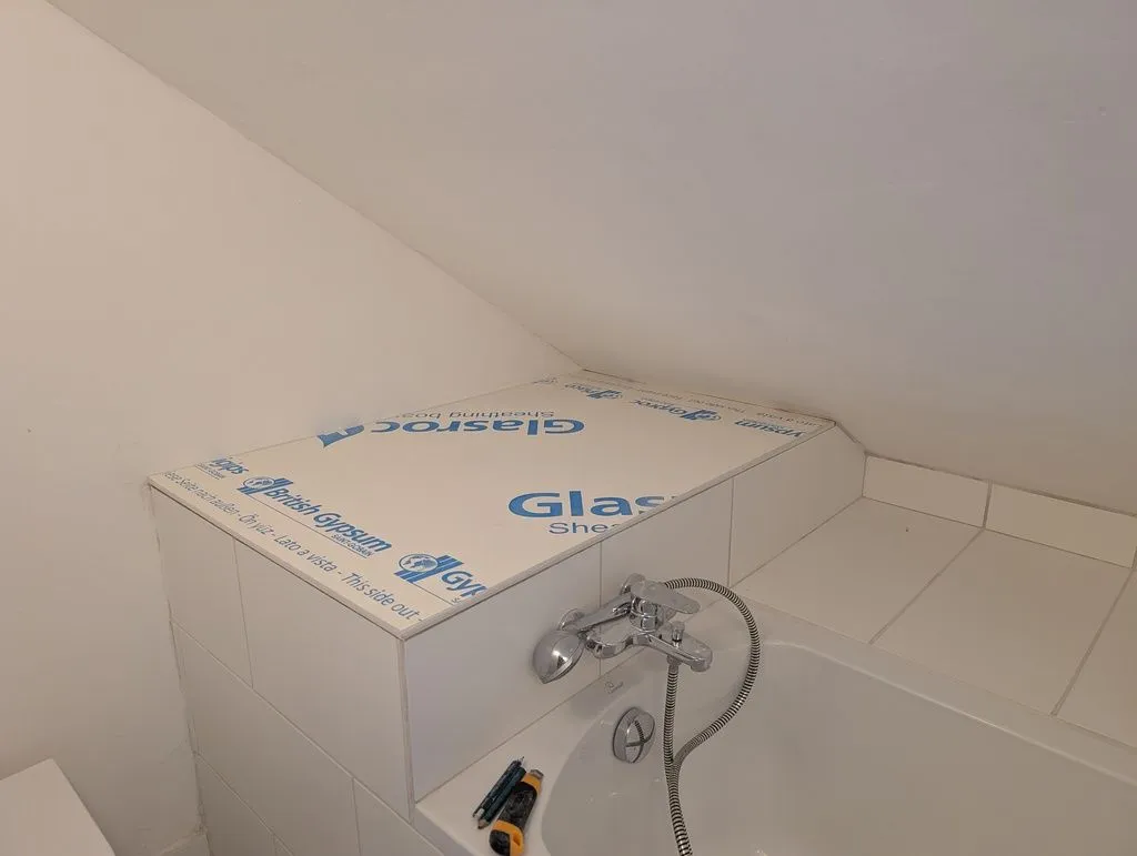
Test-fitting a piece of water-resistant drywall to cover the utility area (there are two columns near the far corner to support the board at all edges).
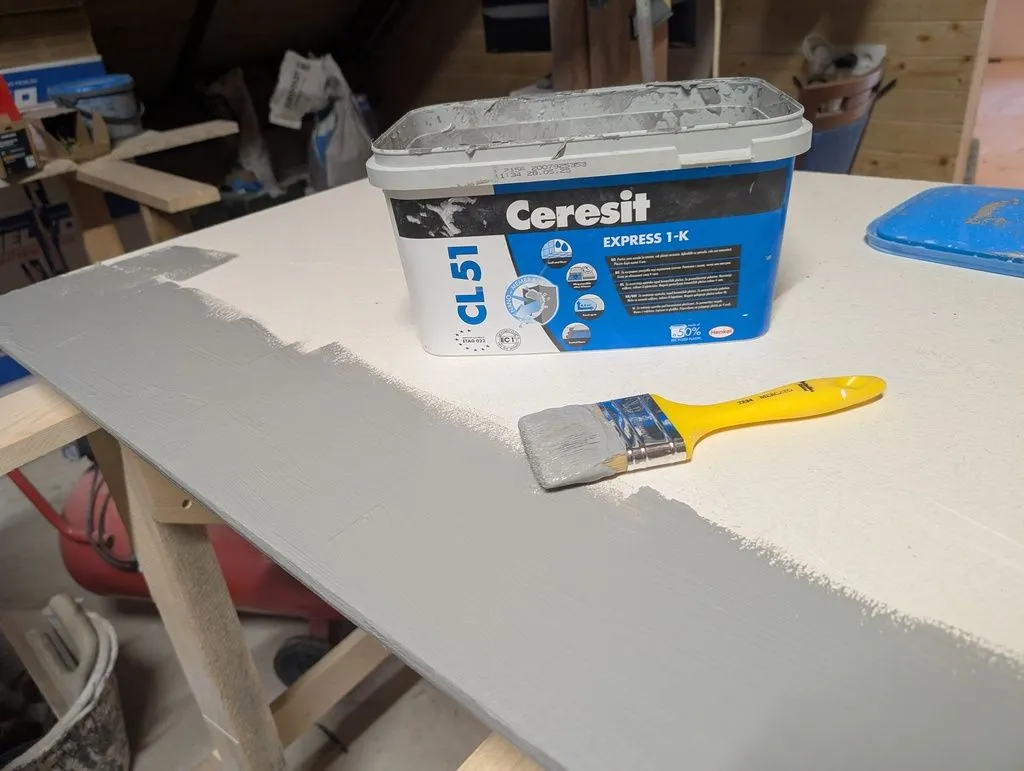
Waterproofing the shelf board.
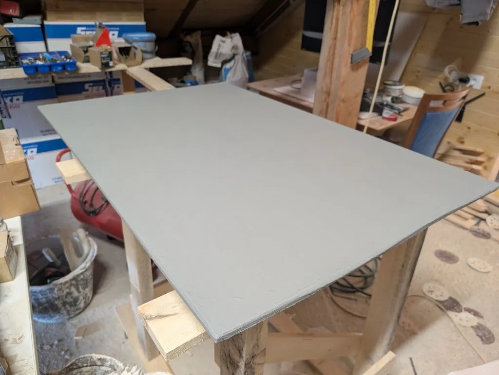
Waterproofing complete.
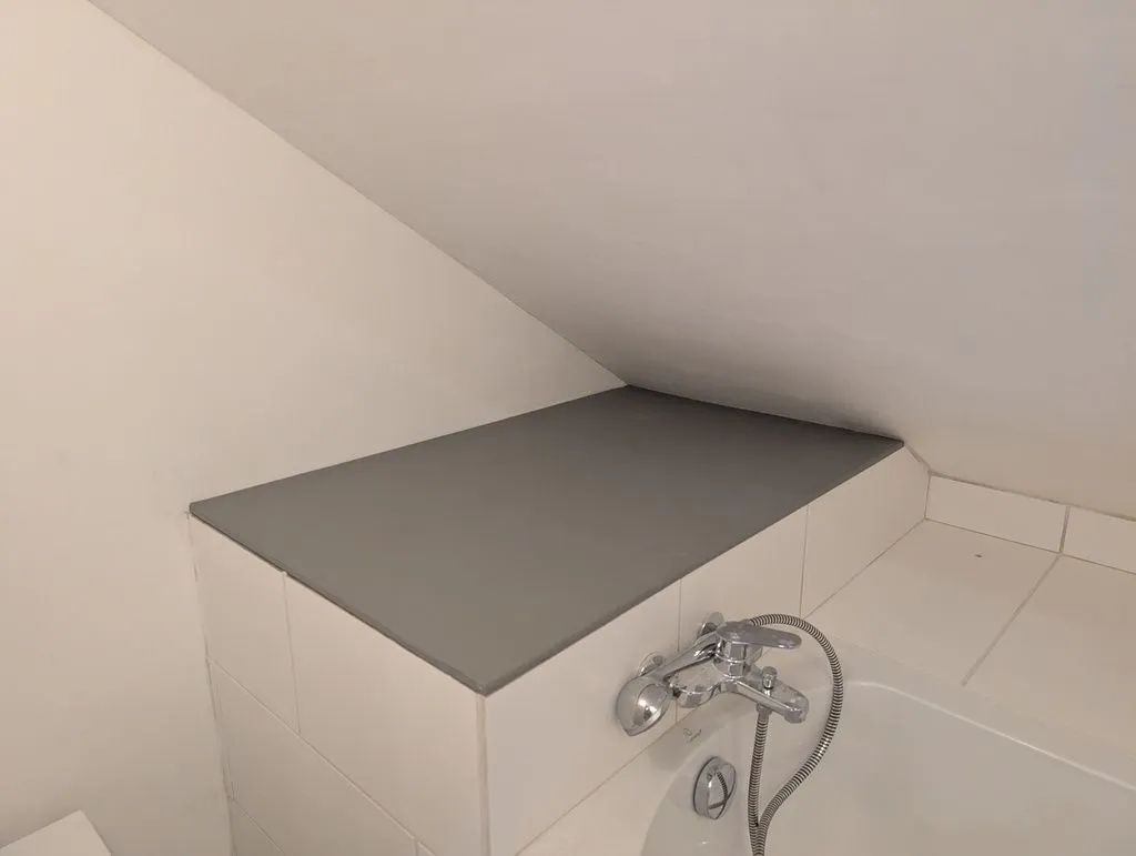
The installed shelf over the utility area. I'll tile it at some point...
Flooring installation
New topic—flooring! We chose wood flooring (20 mm tongue and groove spruce boards) for the interior finish floor. We fastened the boards with countersunk screws driven directly through the faces of the boards into the OSB subfloor. We then filled the screw holes with wood filler.
Aside: the more conventional way to fasten tongue and groove wood flooring is with blind nails through the tongues of each board, with the groove of the next board covering the nails. I found the spruce boards were too susceptible to splitting for this to work well, and the screws through the face did a better job of holding the boards in place, in exchange for more work filling the screw holes later.
The cleaned and vacuumed subfloor ready for finish flooring.
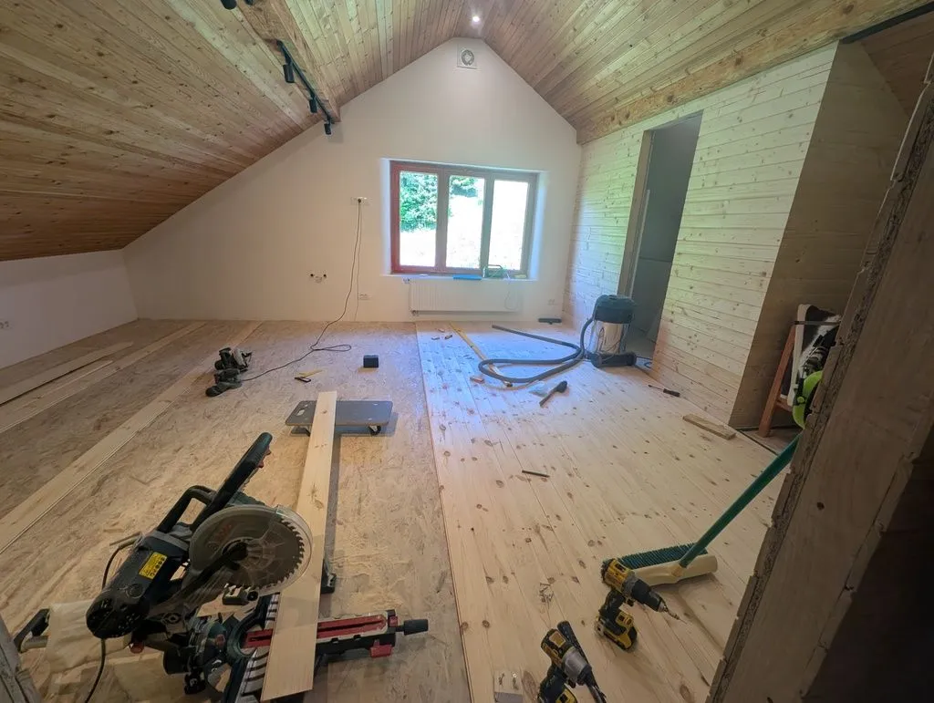
The installation in progress. The miter saw in the foreground was used to cut the boards to length.
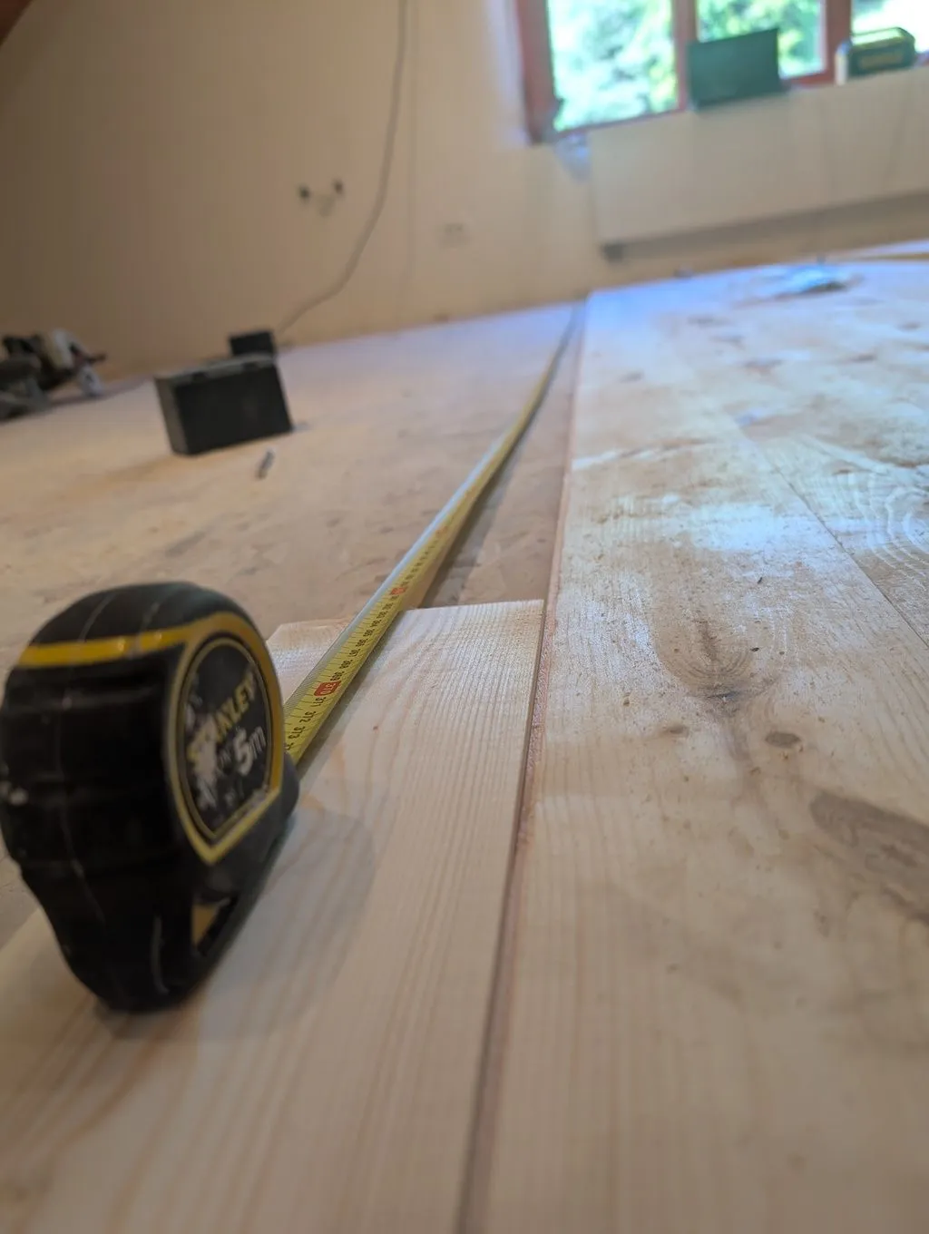
Measuring the length of board needed to complete the current row.
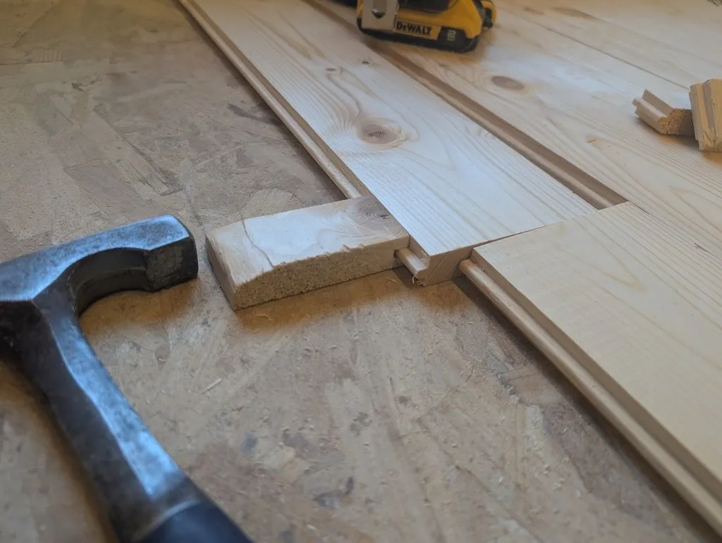
We used a simple jig made from scrap piece of flooring to fit the boards tightly. (Hitting the boards directly with a hammer would cause them to split, but the jig fits over the boards and distributes force sufficiently safely.)
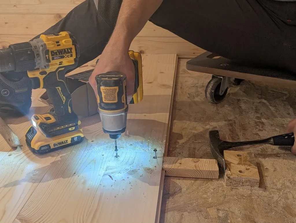
Fastening boards, which we screwed directly through their face into the OSB subfloor. The screws are countersunk at least 5 mm below the surface to allow for future sanding/refinishing. The hammer is being used as a lever to hold the board tightly in place.
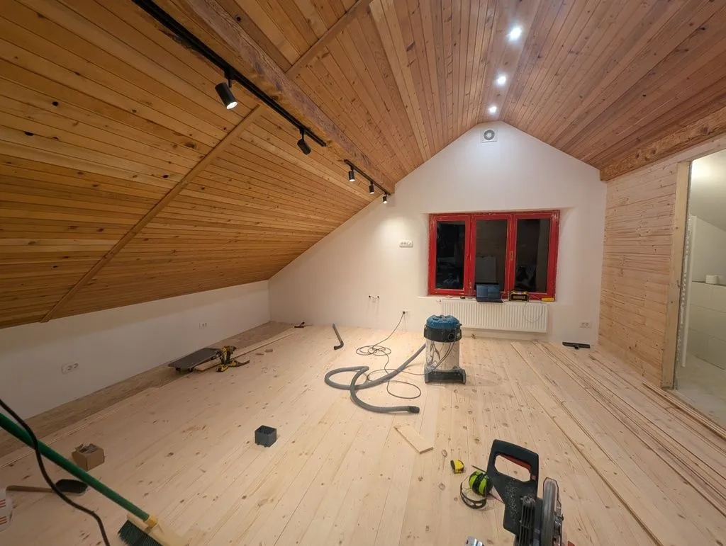
Almost done with the main living area!
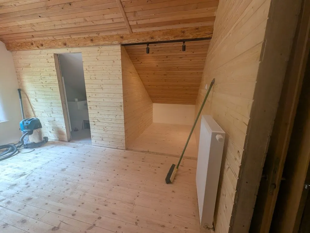
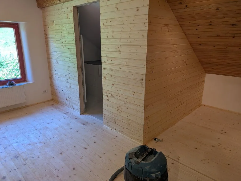
The completed living area and sleeping nook.
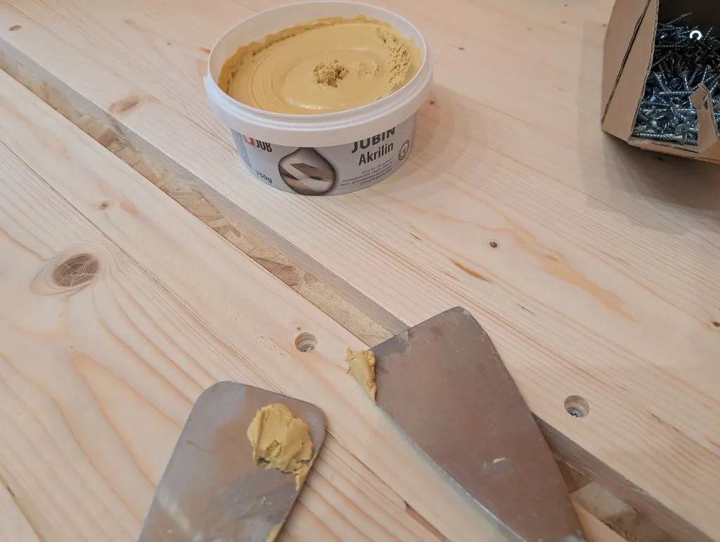
We filled screw holes with Akrilin, a flexible acrylic wood filler made by the Slovenian company JUB.
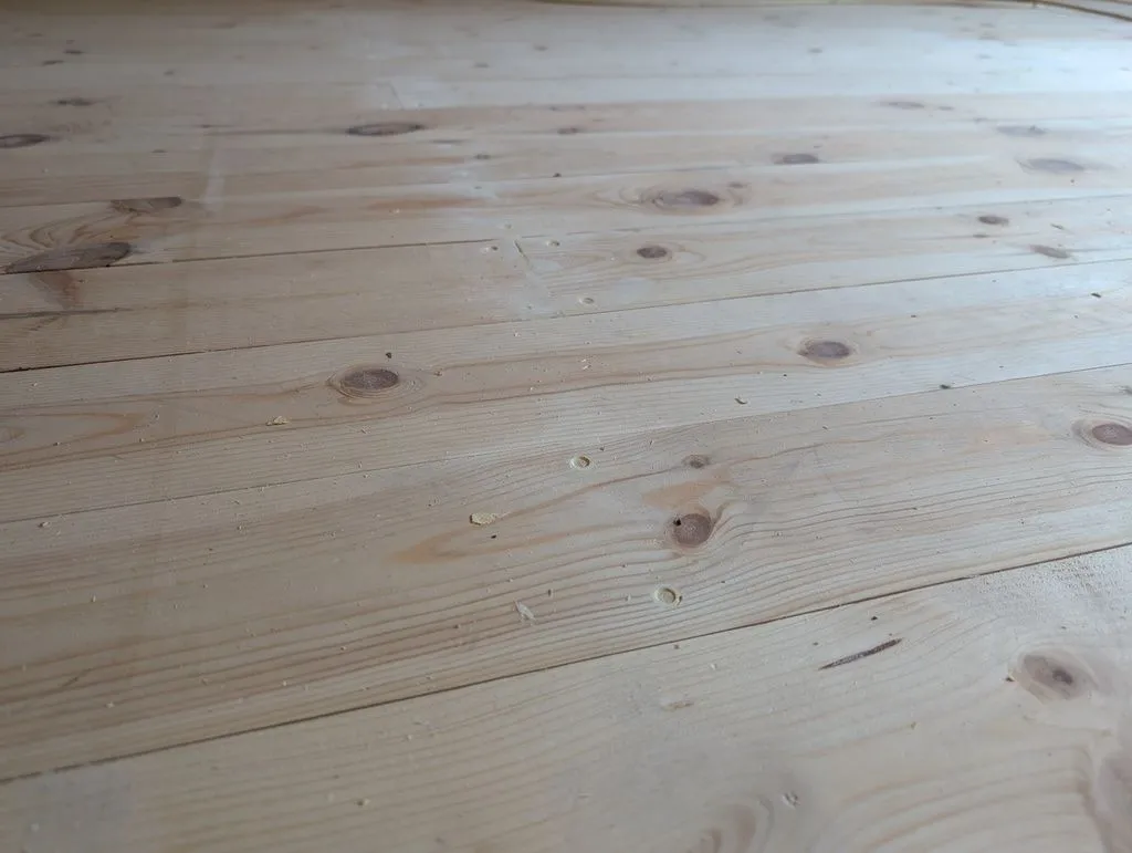
The screw holes after a first application of filler. The filler shrinks slightly, so we applied it in two coats—an initial bulk coat (shown above), followed by a finish coat flush with the surface.
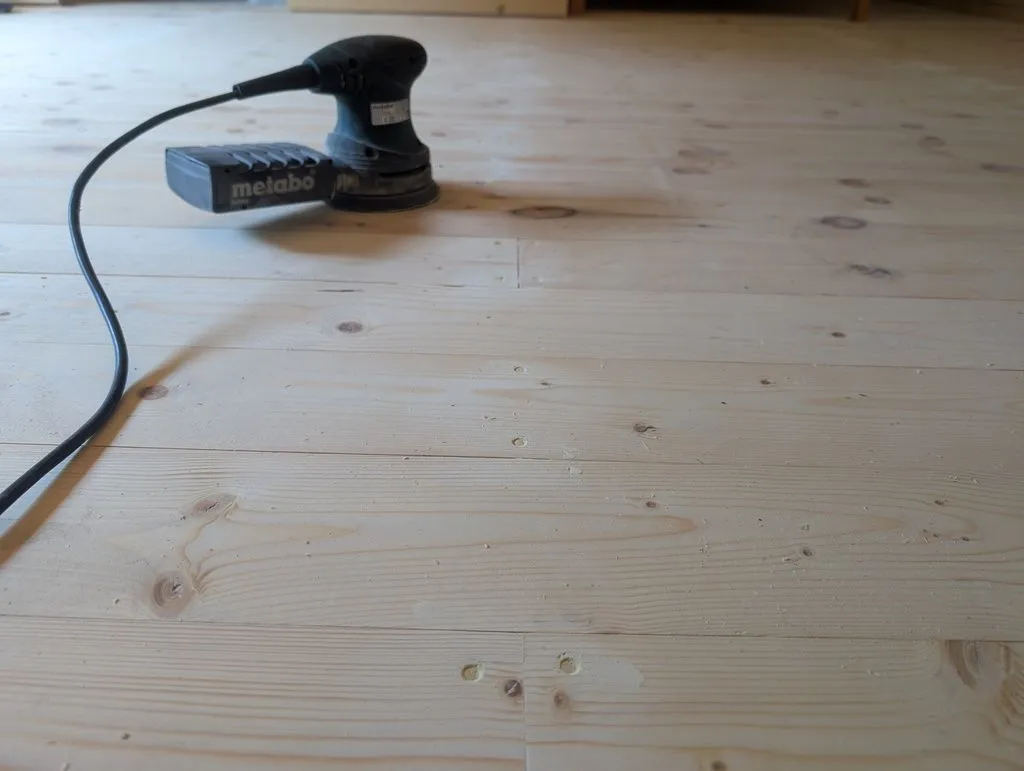
Sanding away filler that made it out of the screw holes between applications.
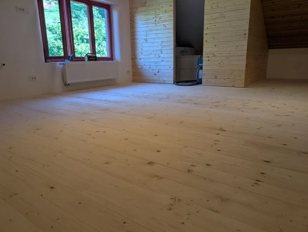
The completed finish floor installation after filling screw holes and sanding.
Finishing the floor
The floor is finished with a water-based polyurethane seal + finish system made by Italian company Chimiver. We left the floors their natural color (i.e. we did not use a stain). The polyurethane finish creates a polymerized protective film on top of floor that should last for many years without maintenance (as opposed to a waxed or natural oil finish, which needs to be renewed regularly). I'm happy with the product—it was practically odorless (being water-based), dried quickly, and preserved the natural character of the spruce boards without the artificial plastic look you'll sometimes see with polyurethane finishes.
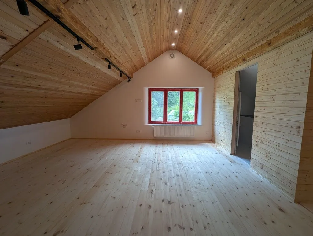
The freshly-installed finish floor, ready for sealing and finishing.
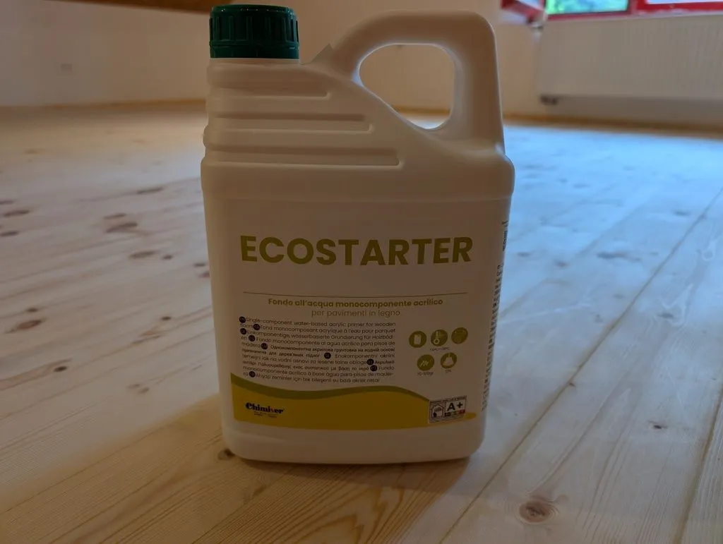
Chimiver Ecostarter, a single-component water-based sealer applied in one or two coats before the finish (we used a single coat). The sealer ensures an even, high-quality finish result.
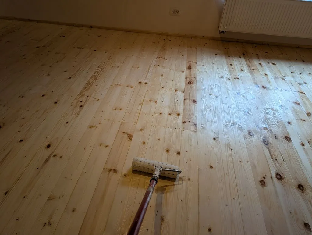
Applying the sealant with a microfiber roller.
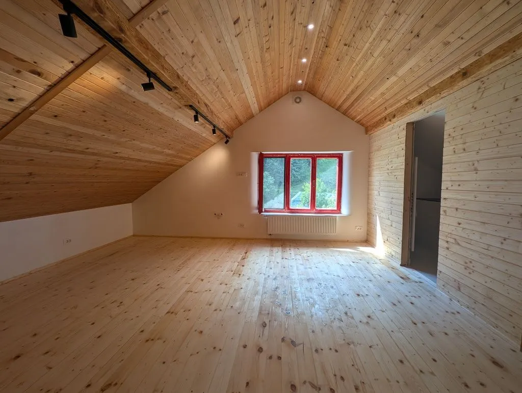
The sealed floor, still largely its natural color and luster, as desired.
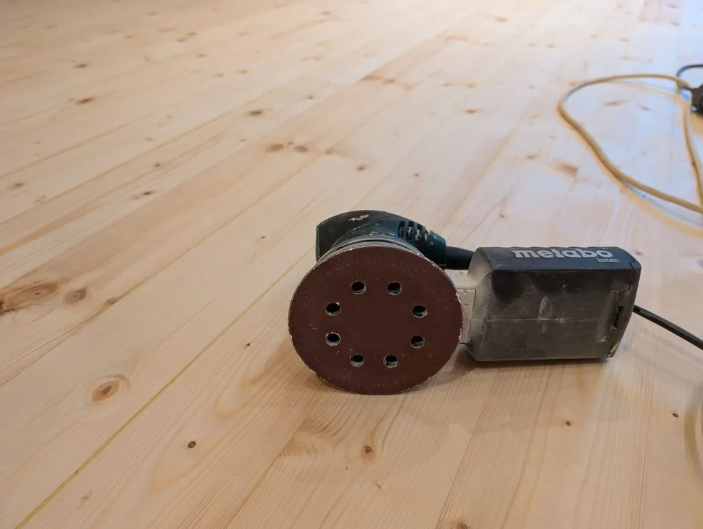
The floor is sanded briefly with a high-grit sandpaper between every coat of sealer and finish. This mechanically scuffs up the previous coat at a miscroscopic level to ensure a better bond of the next coat.
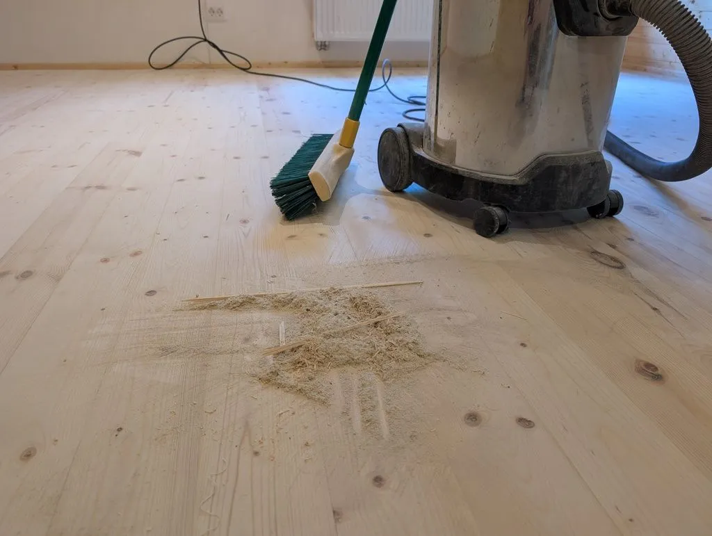
The floor must be thoroughly cleaned between coats: we first swept up sanding dust with a broom and cleaned the floor with a shop vac...
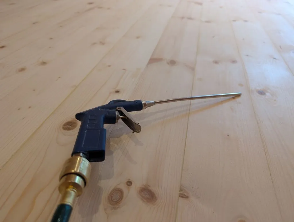
...then used compressed air to blow away any trace dust.
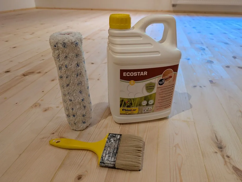
Chimiver Ecostar, a single-component water-based finish (they call it a lacquer, but this is European terminology; it would be called finish in the USA). The finish is applied in two or three coats using a brush or microfiber roller, with sanding between coats.
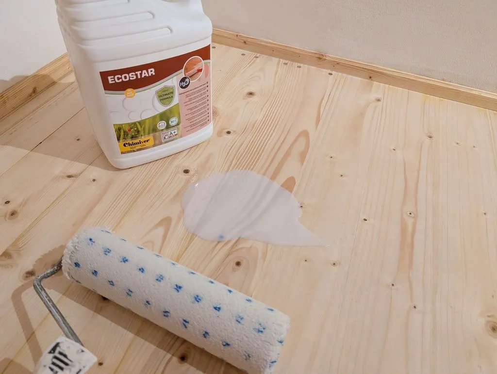
The finish is milky white color when poured out of the jug, but is colorless when it cures.
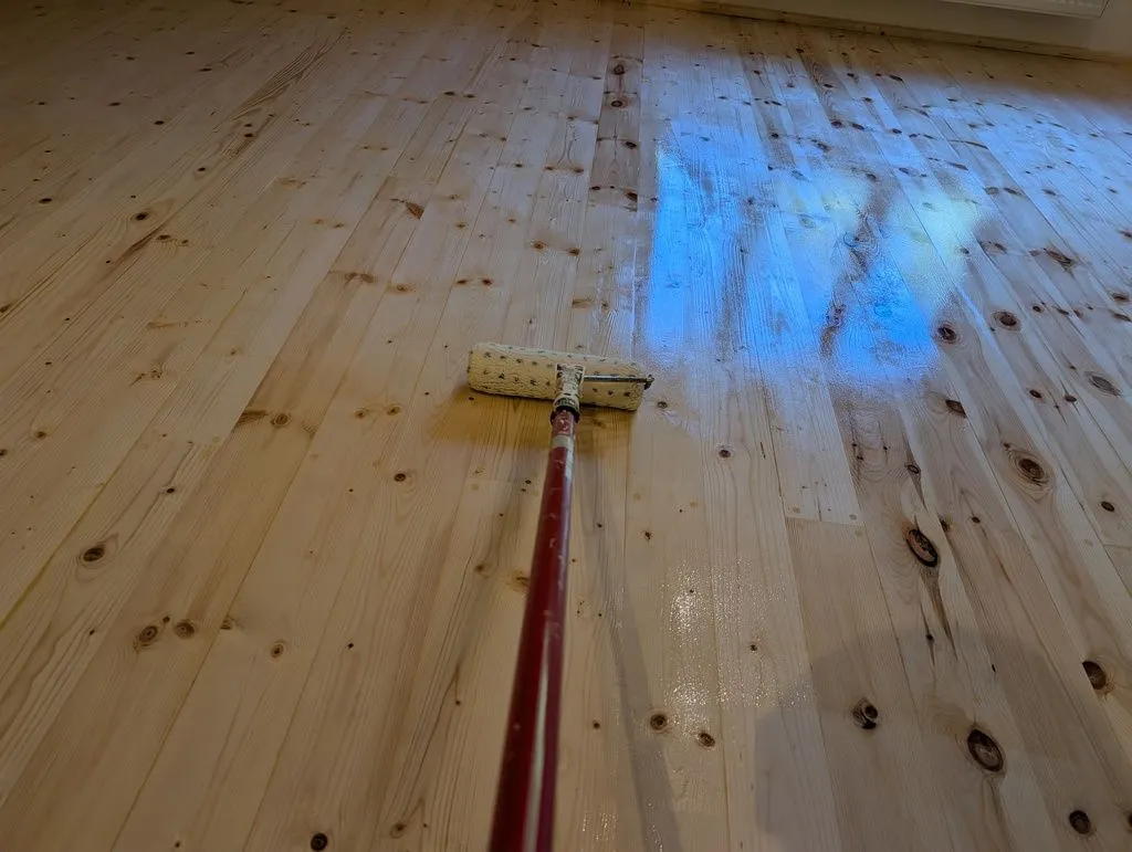
Applying the first coat of floor finish with a microfiber roller.
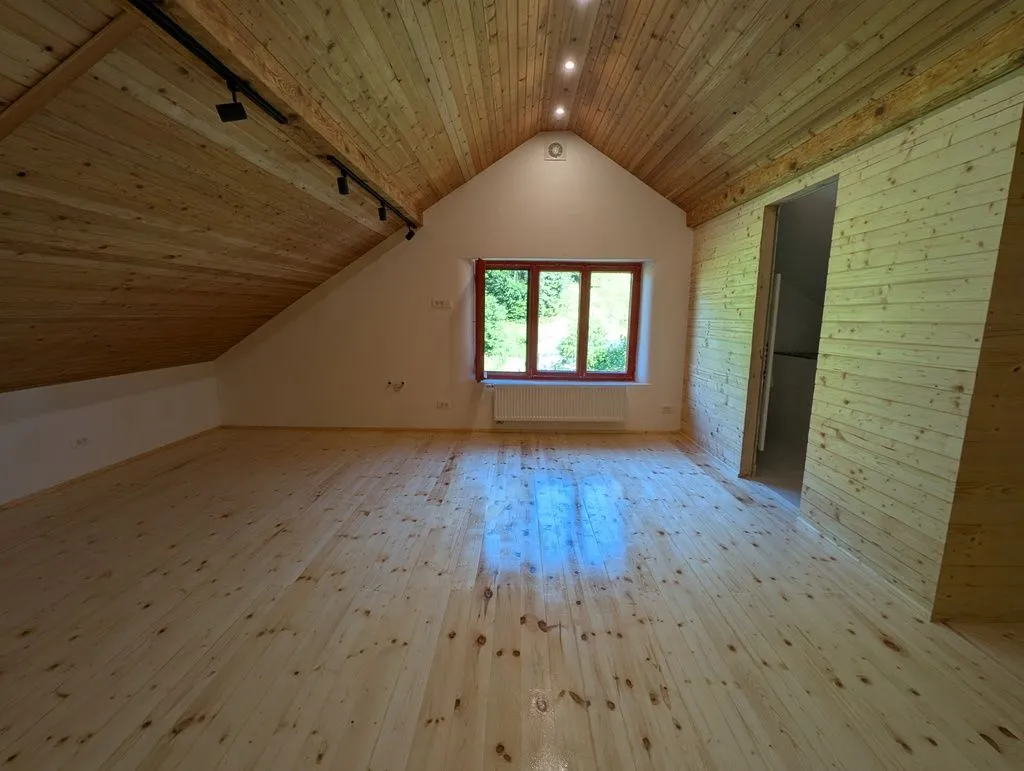
The completed first coat of finish. It is still wet and so appears high-gloss, but dries to a matte luster.
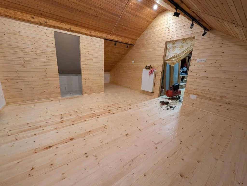
The complete finished floor after intermediate sanding and another coat of finish.
Finish carpentry: floor skirting/baseboards
We finished the perimeter of the floor with simple skirting made from the same locally-sourced spruce stock as the tongue and groove boards used for the wall finish. The boards are already planed and sanded, and we just ripped them to width and milled the simple profile ourselves with a hand router.
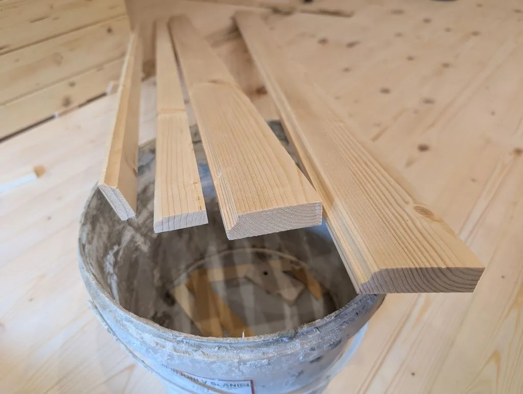
R&D: testing out various board thicknesses and profiles to find the one we liked best.
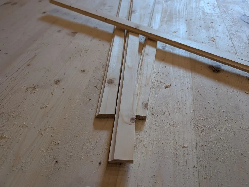
We settled for a simple coved profile and 12 mm boards.
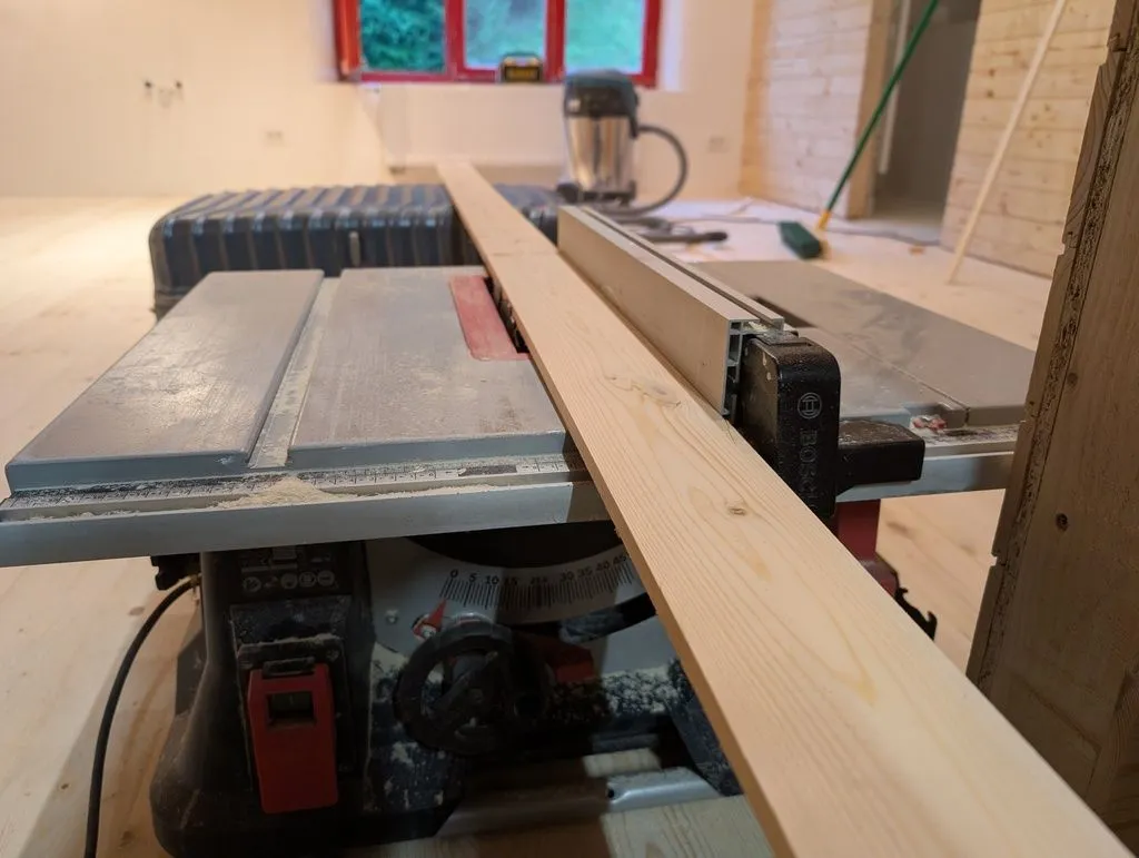
Ripping the boards to width on the table saw. We used the same stock as for the tongue and groove wall finish.
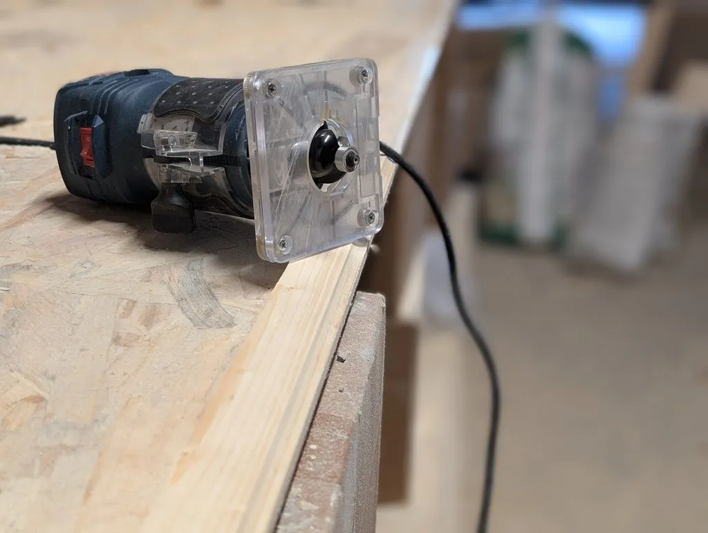
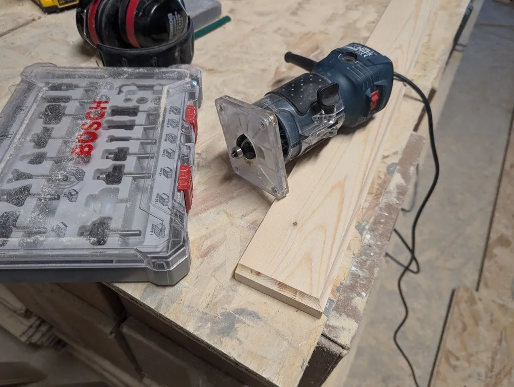
We milled the profile with a coved bit and a hand router.
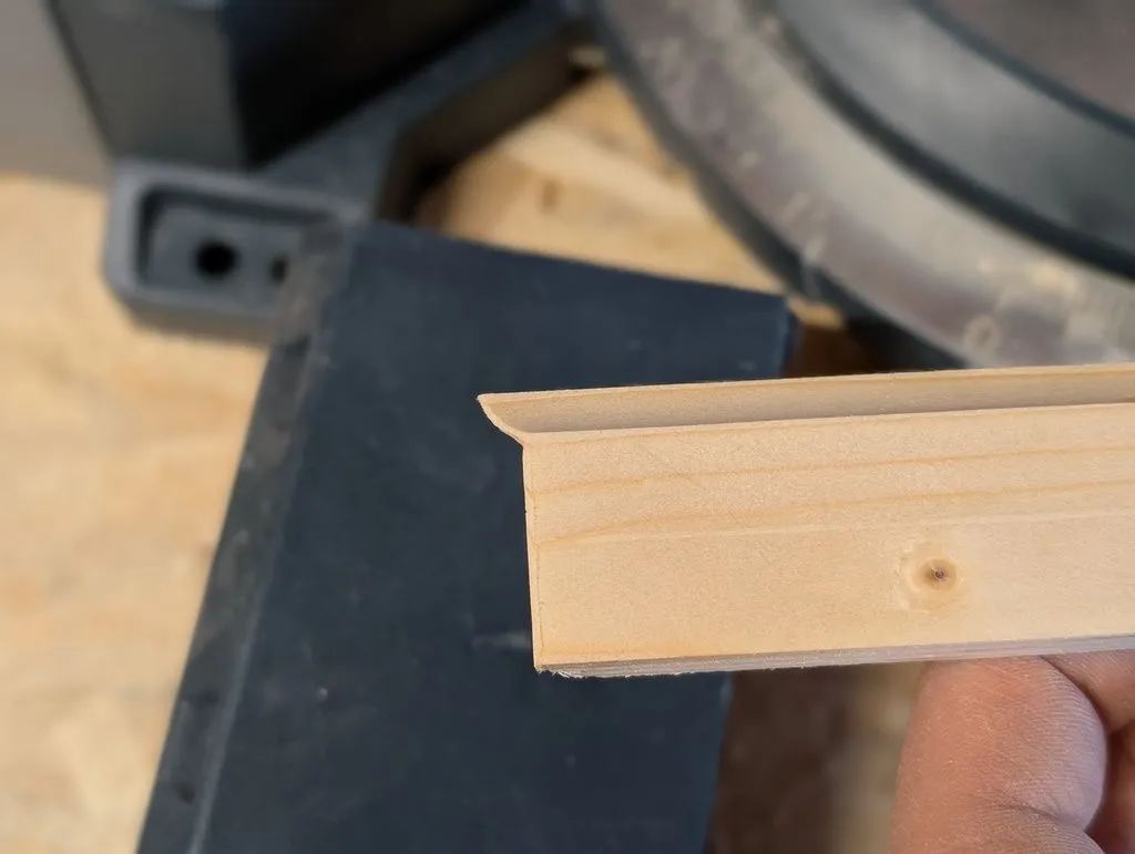
A coped end used to make an interior corner.
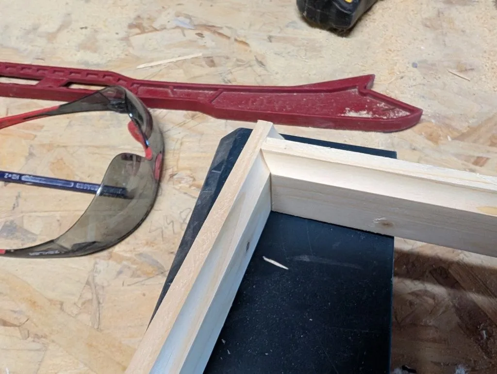
Test-fitting the coped joint.
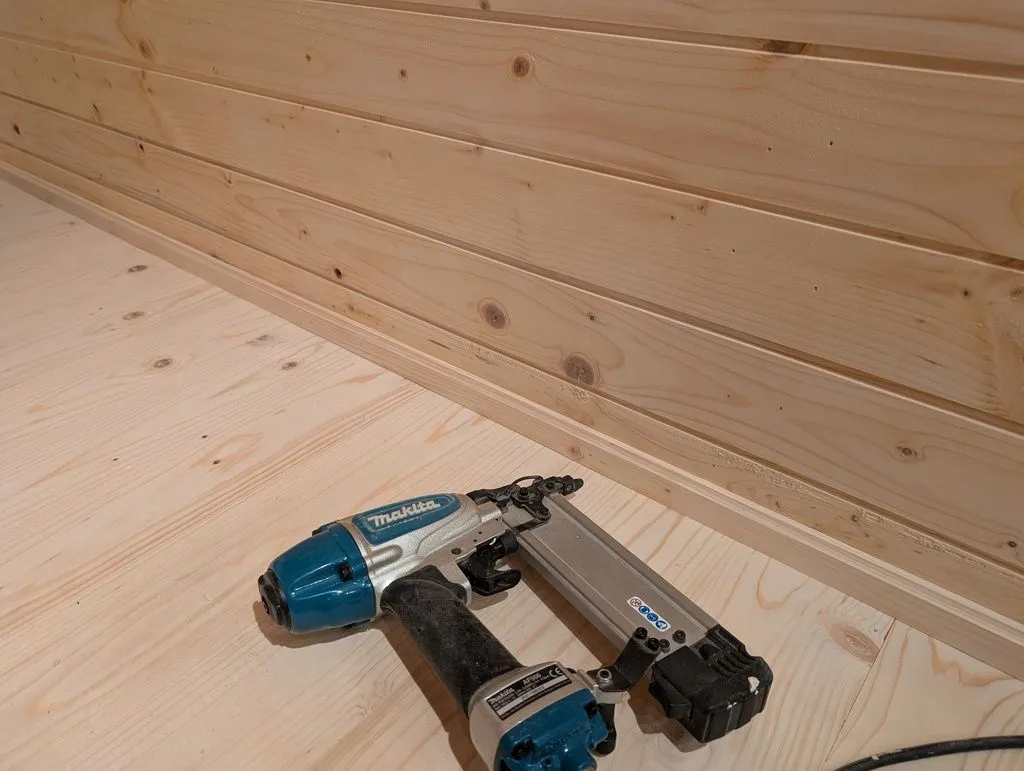
Attaching the baseboards to the wall using an 18 gauge brad nailer.
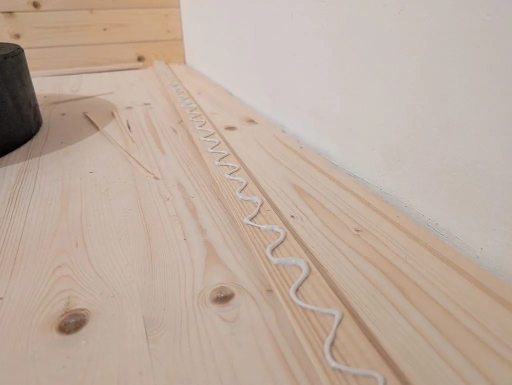
We attached the boards with construction adhesive in the masonry portions of the wall, which would not accept fasteners.
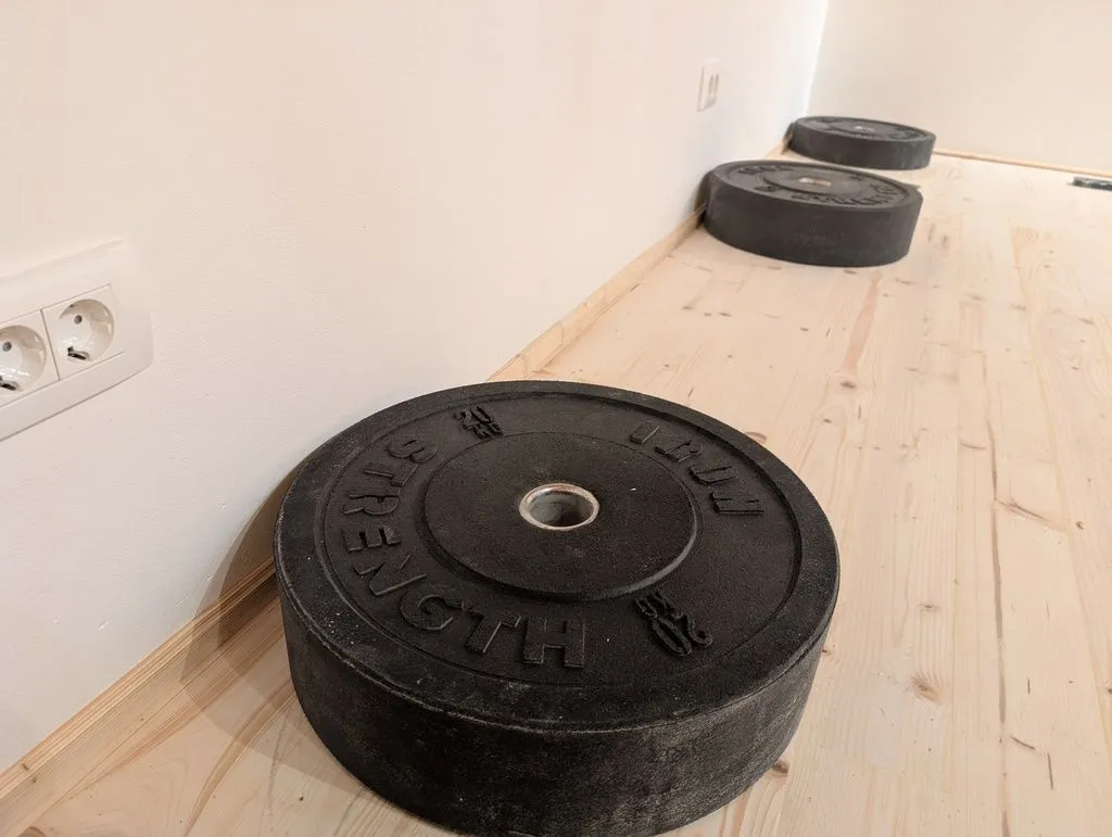
Using weights to hold the baseboards in place while the adhesive cures.
The completed baseboards—they are simple and unobtrusive.
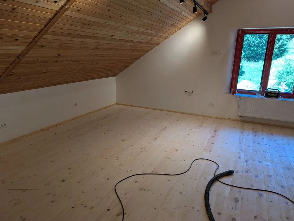
The completed baseboards in the far corner of the living area.
Aside: refitting hinges
We used old doors we had salvaged from a previous apartment, but did not have the old hinges. The holes in the doors from the previous hinges were too large for the new hinges we would use; this section shows the process of filling the old holes and installing the new hinges.
Aside: this style of hinge is common on simple interior doors in Slovenia, and is probably unfamiliar to US readers familiar with the usual butt hinges.
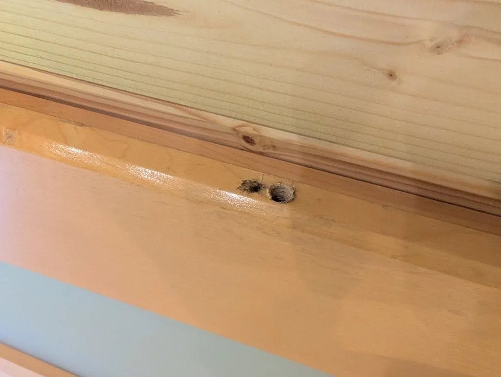
The hole in the door from the old hinge was too large for the new hinges we would use, and would have to be filled.
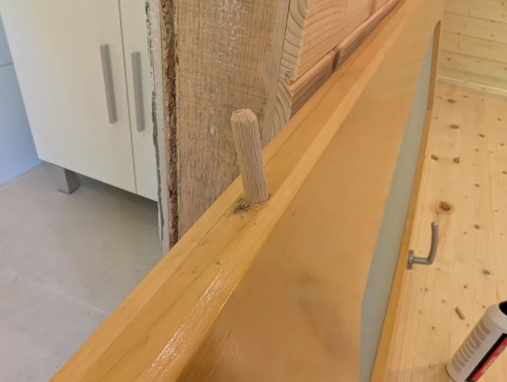
Filling the existing hole with a hardwood dowel, which is glued in place and left to sit until the glue dries.
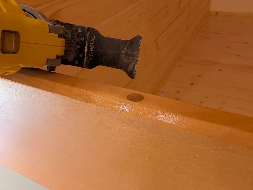
Cutting the dowel flush with the surface of the door. A flexible fine-toothed Japanese hand saw is the correct tool for the job, but I did not have one on hand, and made due with an oscillating multitool.
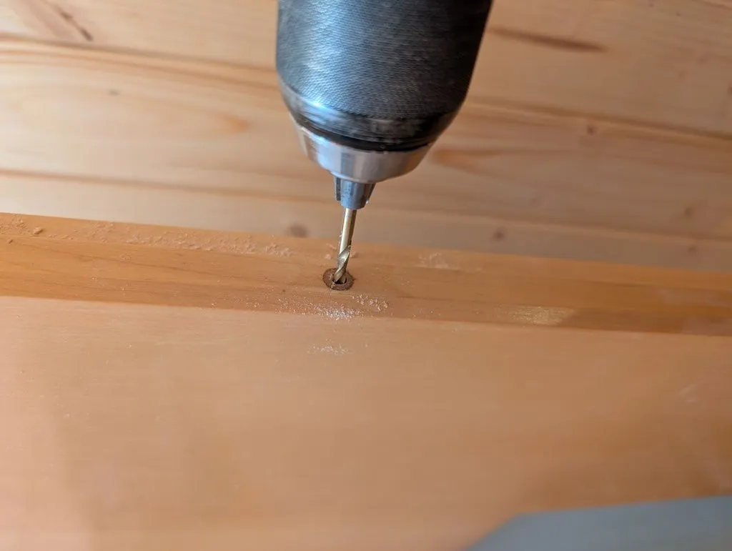
Drilling a starter guide hole with a thin-diameter drill bit.
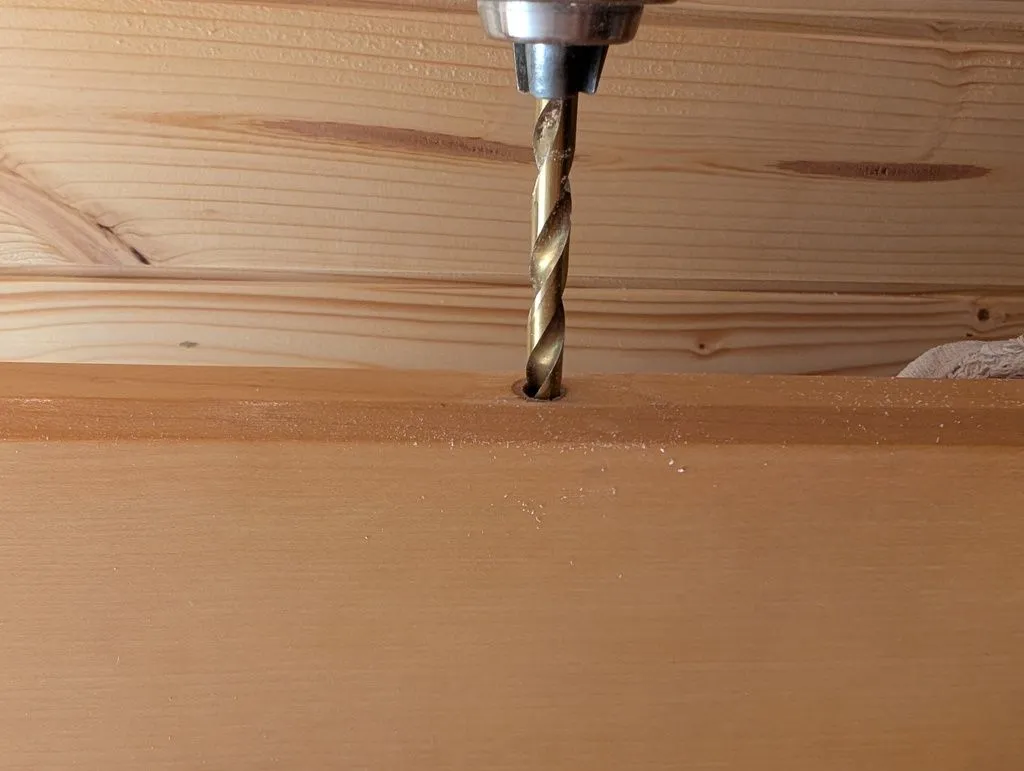
Drilling the correct diameter pilot hole for the new hinges.
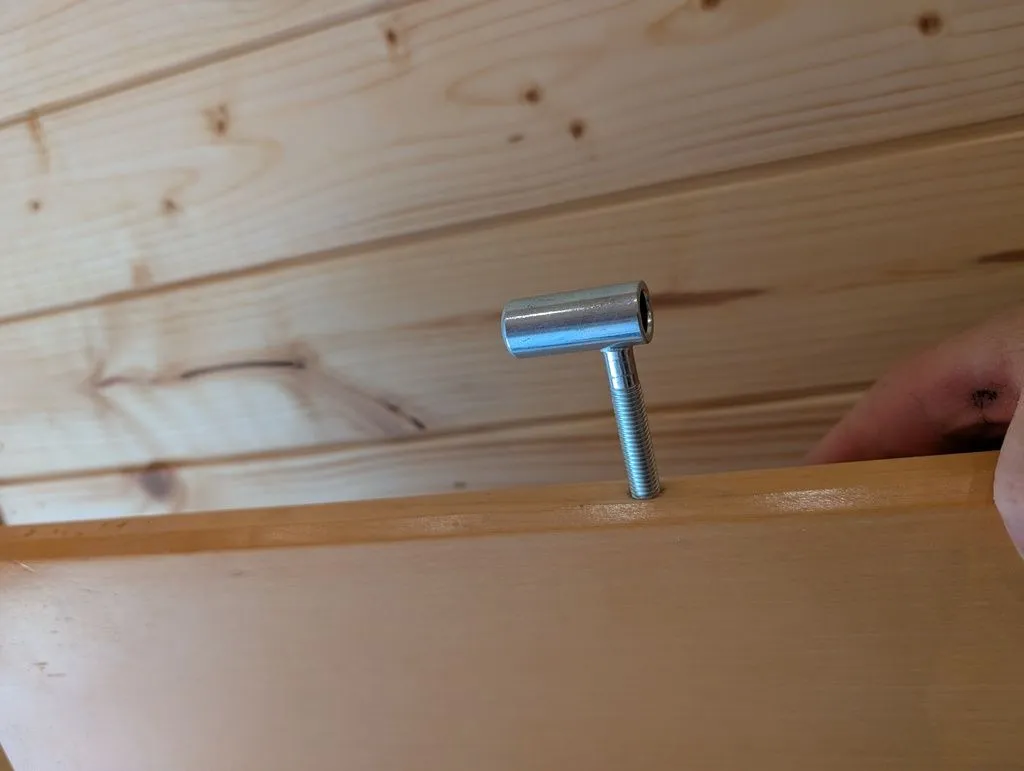
The new hinge is screwed into the new pilot hole and fits over a matching pin in the door jamb.
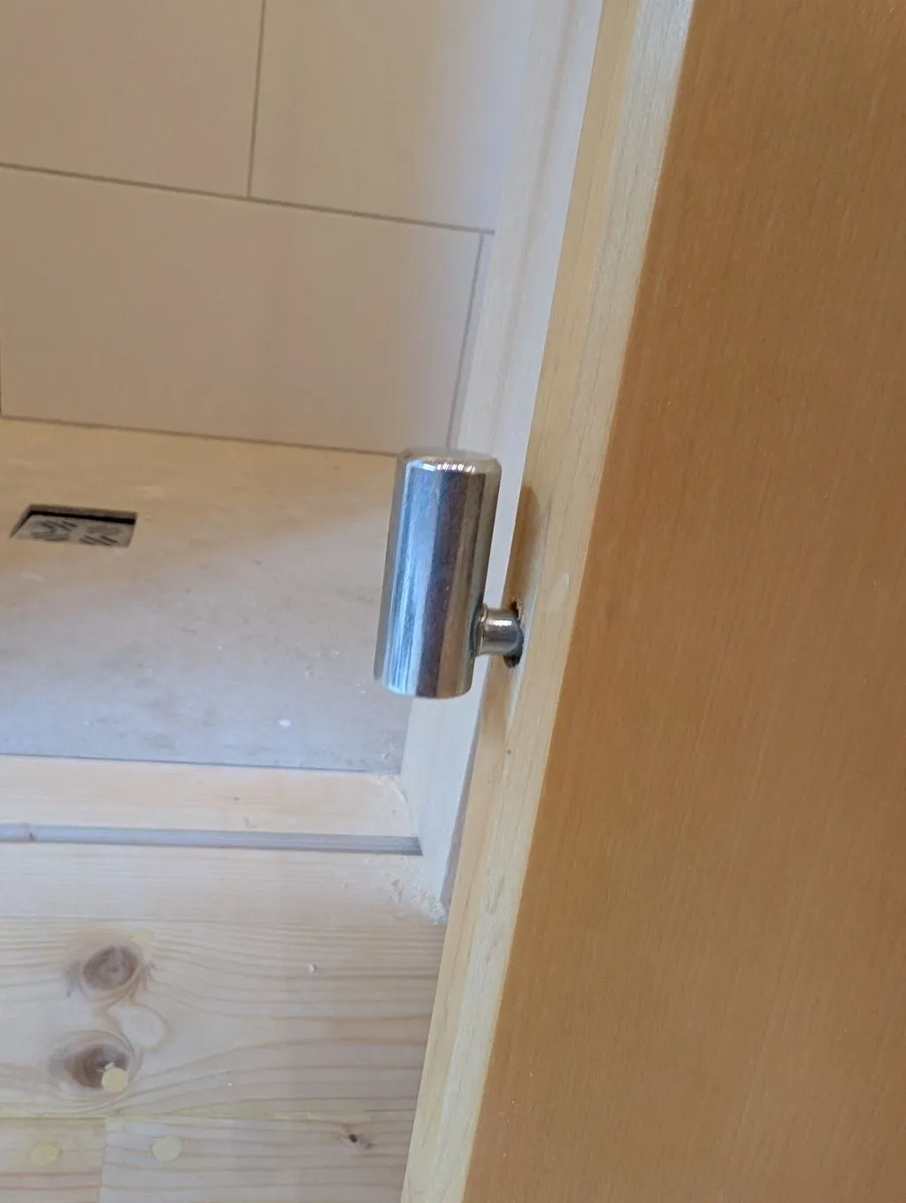
The new hinge installed. The door is now ready to be hung.
Installing interior doors
We reused old doors we had salvaged from a previous apartment, which left us with fond memories and many hundreds of euros in our pockets (doors are expensive!). We built new jambs to match the existing doors.
Fun aside: we built the jambs with lumber milled from our own forest, and jointed and thickness planed for me by our neighbor (I have neither a jointer or a thickness planer, but my neighbors are both better equipped and gracious with their tools!).
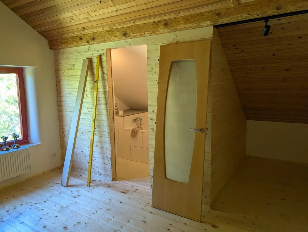
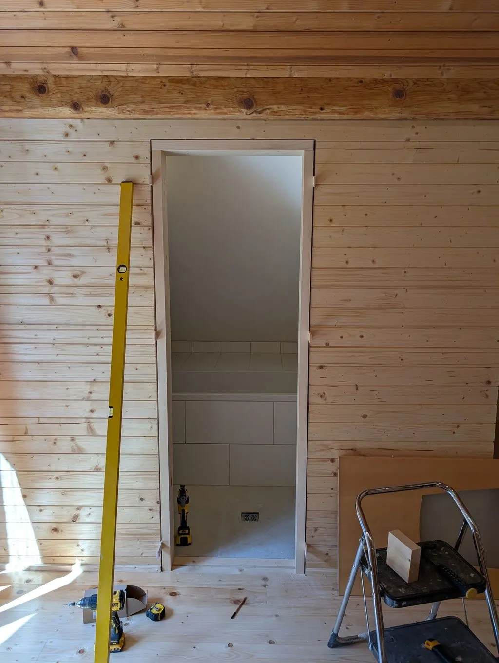
The bathroom rough opening and door, ready for installation.
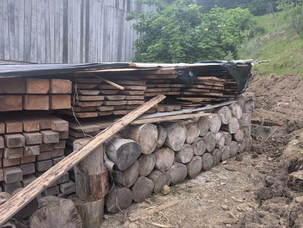
Our stack of lumber (mostly spruce—the dominant construction softwood in Slovenia and much of Central Europe), from which we made the door jambs. The jambs are made from nominally 50 mm boards, which were jointed and then planed to 40 mm.
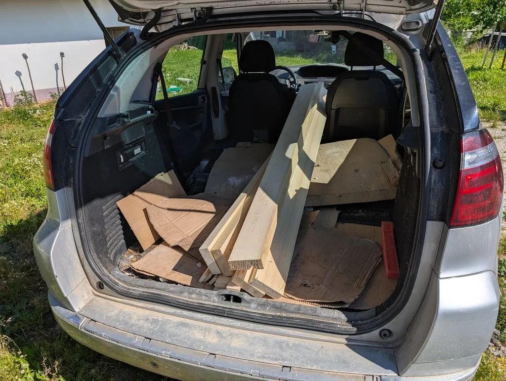
The jointed and planed jambs, freshly picked up from my neighbor, who processed them for me. (As mentioned in the introduction, I have neither a jointer nor a thickness planer, but my neighbors are better equipped and gracious with their tools!)
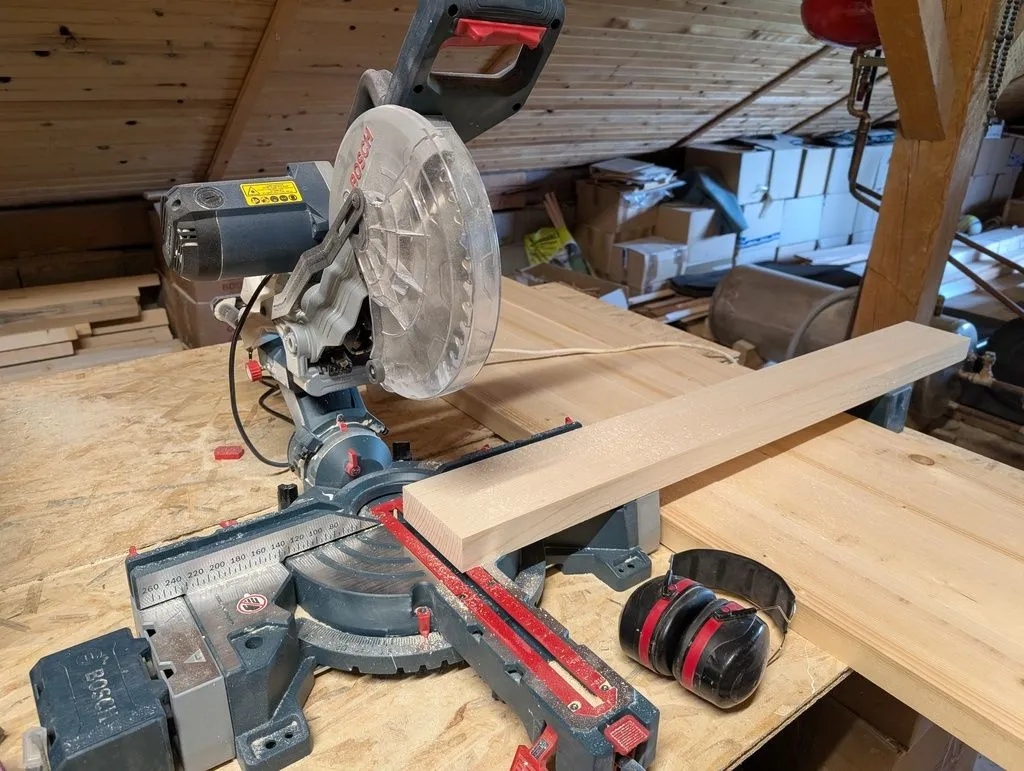
Cutting the jambs to length on the miter saw...
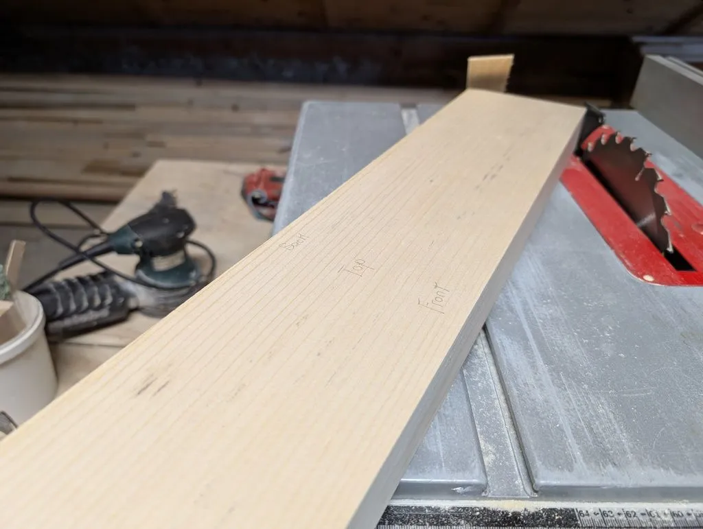
...and to width on the table saw.
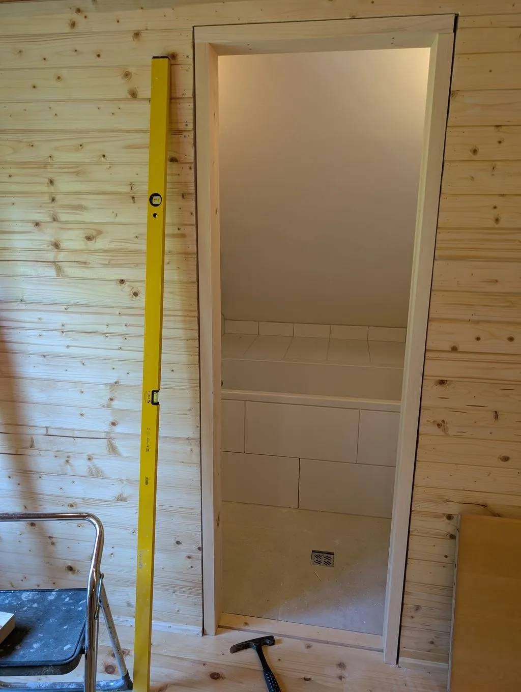
Test-fitting the jambs before attaching them. I left a roughly 8 mm gap between the rough opening and jambs. The test fit looks good!
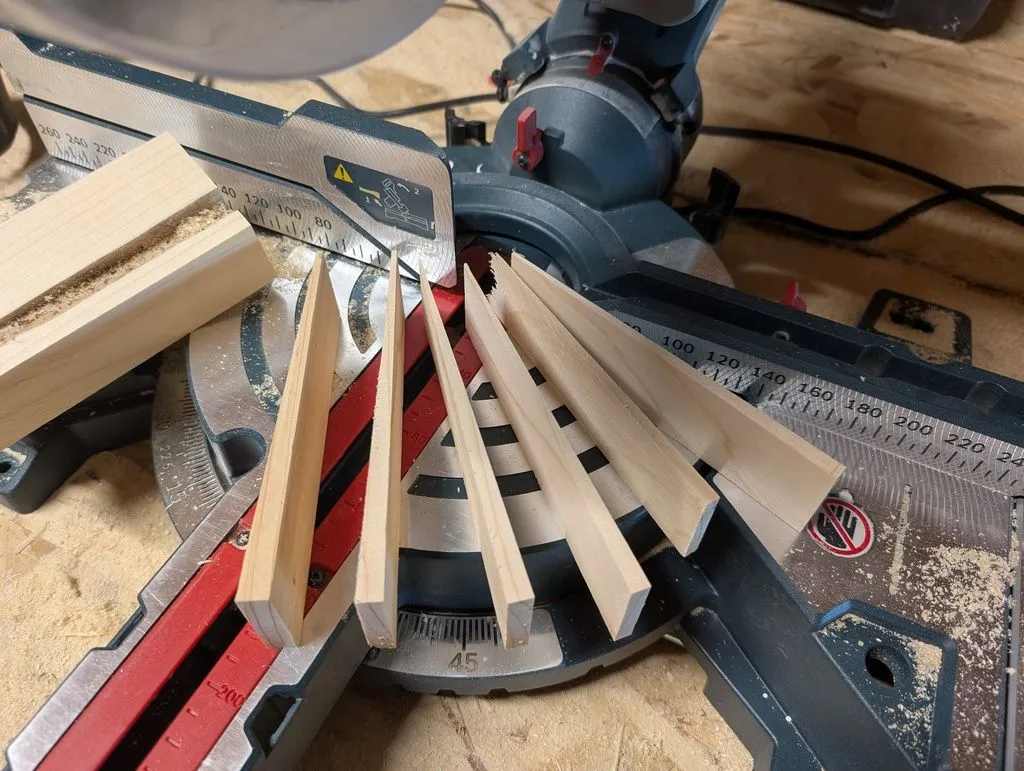
Cutting shims on the miter saw. I would use these shims to plumb and level the jambs.
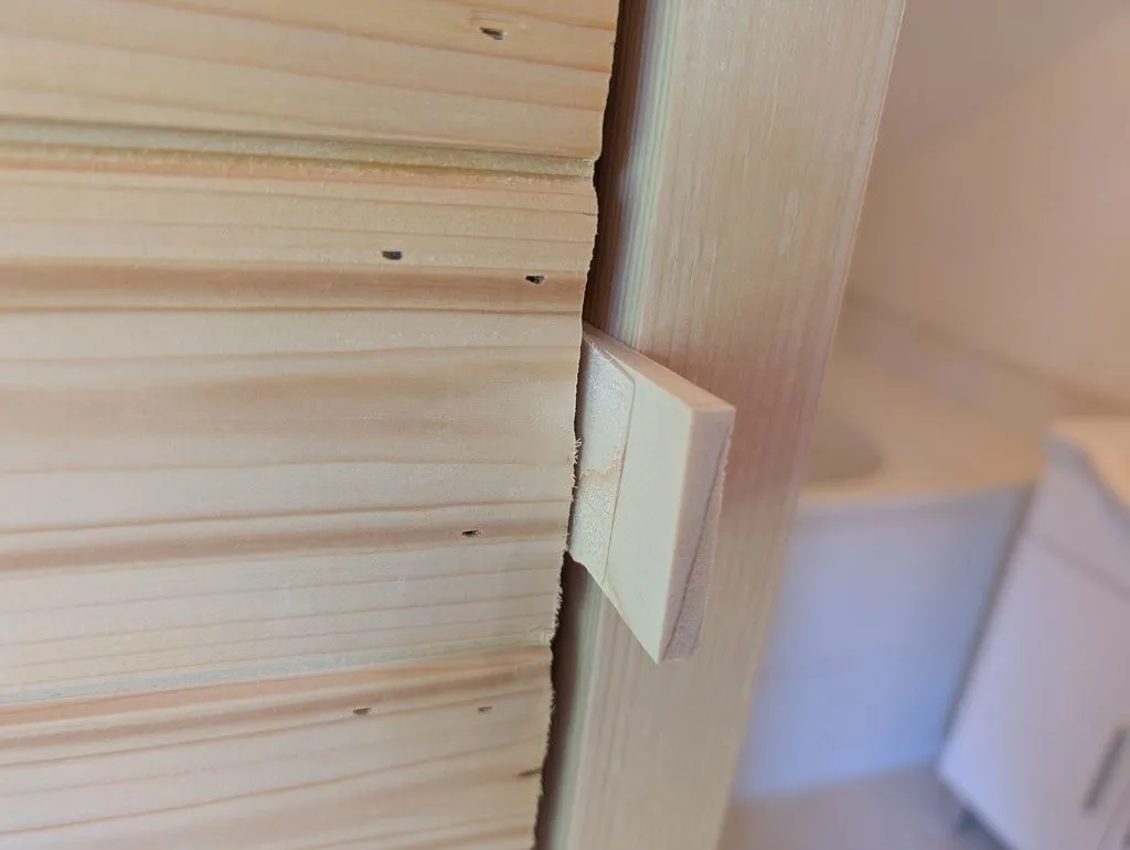
Shims are used to plumb and level the side and top jambs, and to provide mechanical support the jambs where they are screwed into the framing.
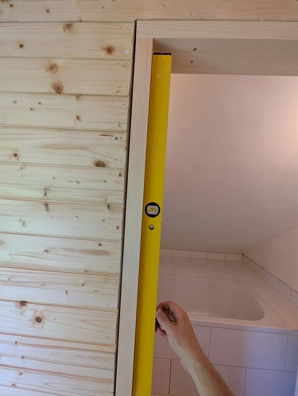
Ensuring the side jambs are plumb before attaching them.
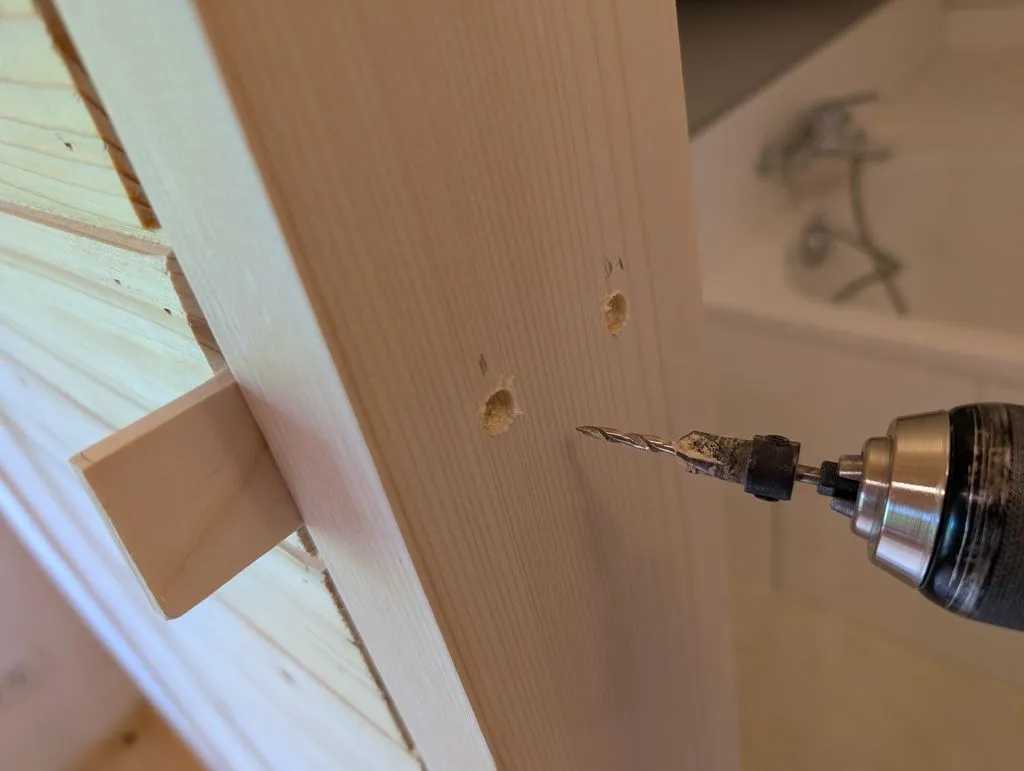
Attaching the side jambs—we used countersunk construction screws, and later filled the screw holes with wood filler.
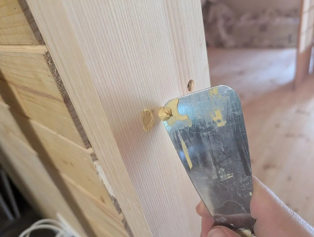
Filling the screw holes with wood filler.
The completed jambs for the bathroom door.
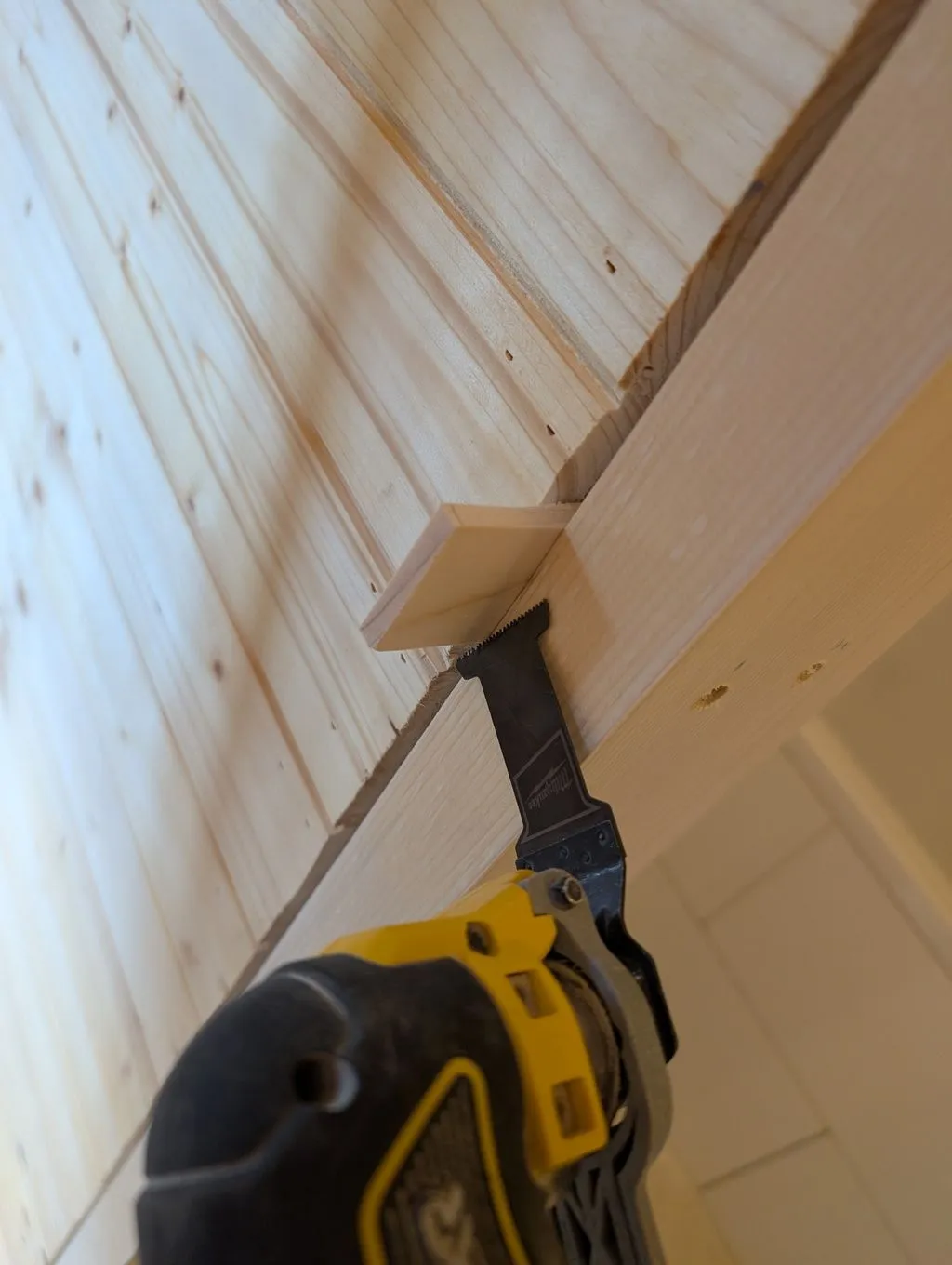
Cutting away the protruding parts of the shims with an oscillating multitool after attaching the jambs.
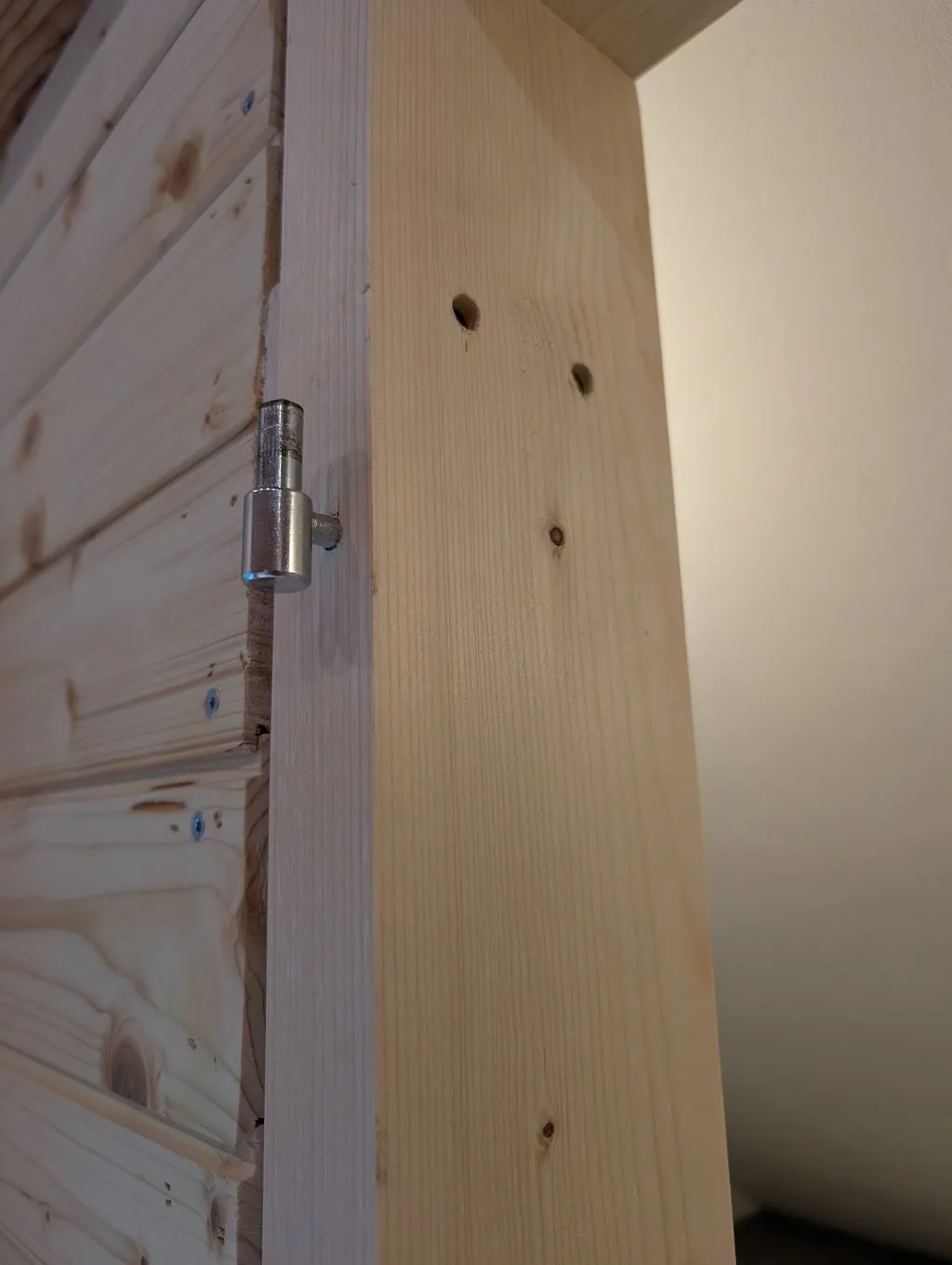
Attaching the hinges to the jambs. Matching hinges on the door fit over and pivot on the pin hinges in the jambs. These hinges are simple and don't allow any adjustment, so they have to be accurately placed.
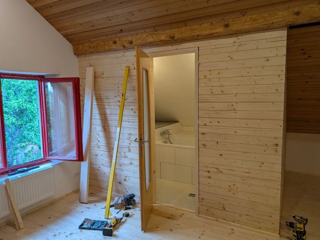
Testing the door operation after hanging the door.
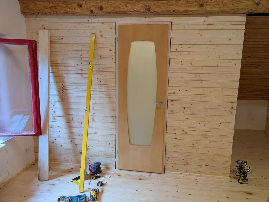
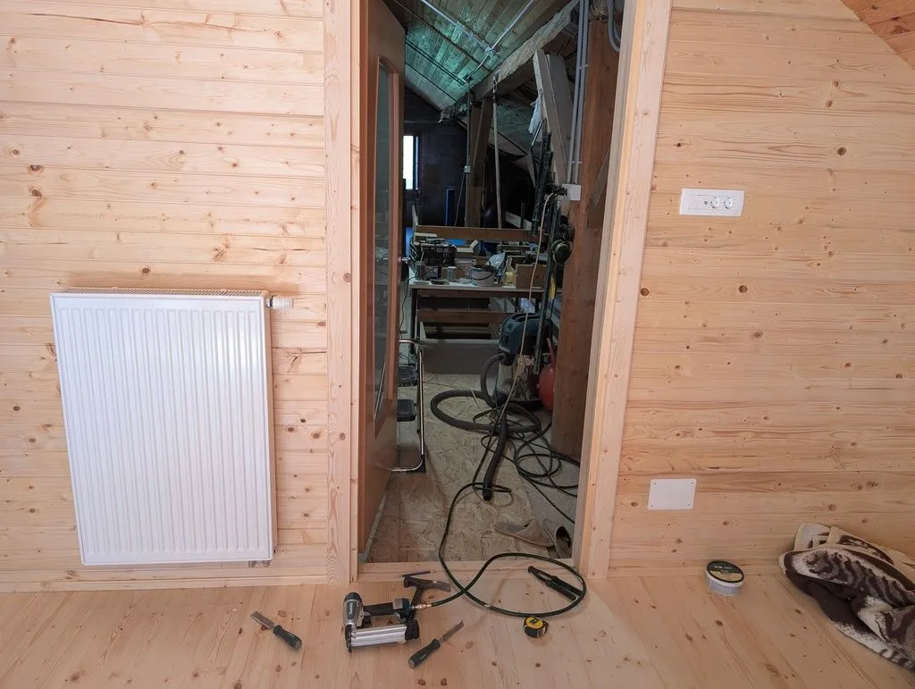
All done! The bathroom door successfully hung.
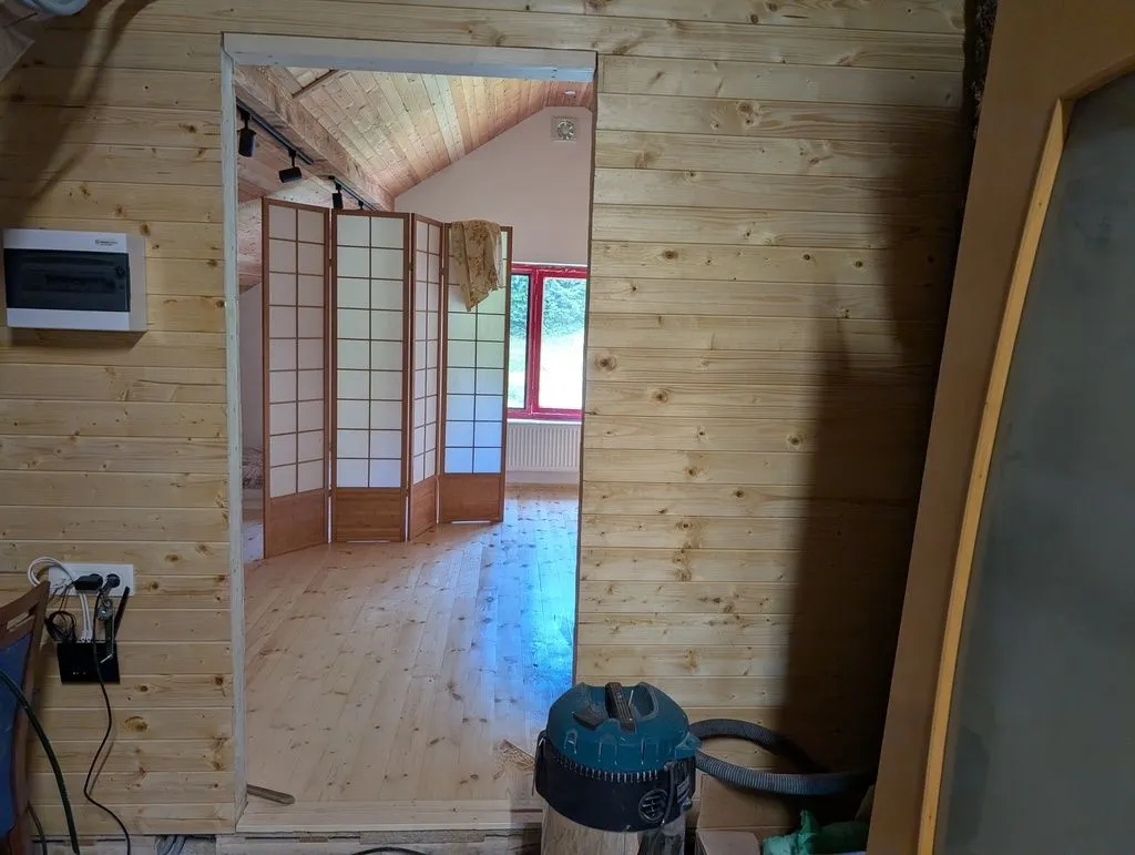
The rough opening for the main entry door into the attic living space.
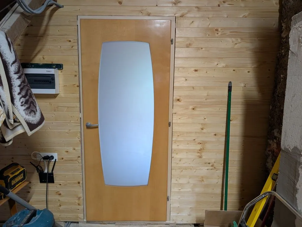
The main entry door hung. The process of building the jambs and hanging the door is analogous to the process for the bathroom door; here is the finished result.
Finish carpentry: door casings
The door casings, which cover the gap between the door jambs and rough opening, are made from the same 20 mm spruce stock as the finish floor. We made simple butt casings with a coved profile. Like for the baseboard, the boards are already planed and sanded, and we just ripped them to width and milled the simple profile ourselves with a hand router.
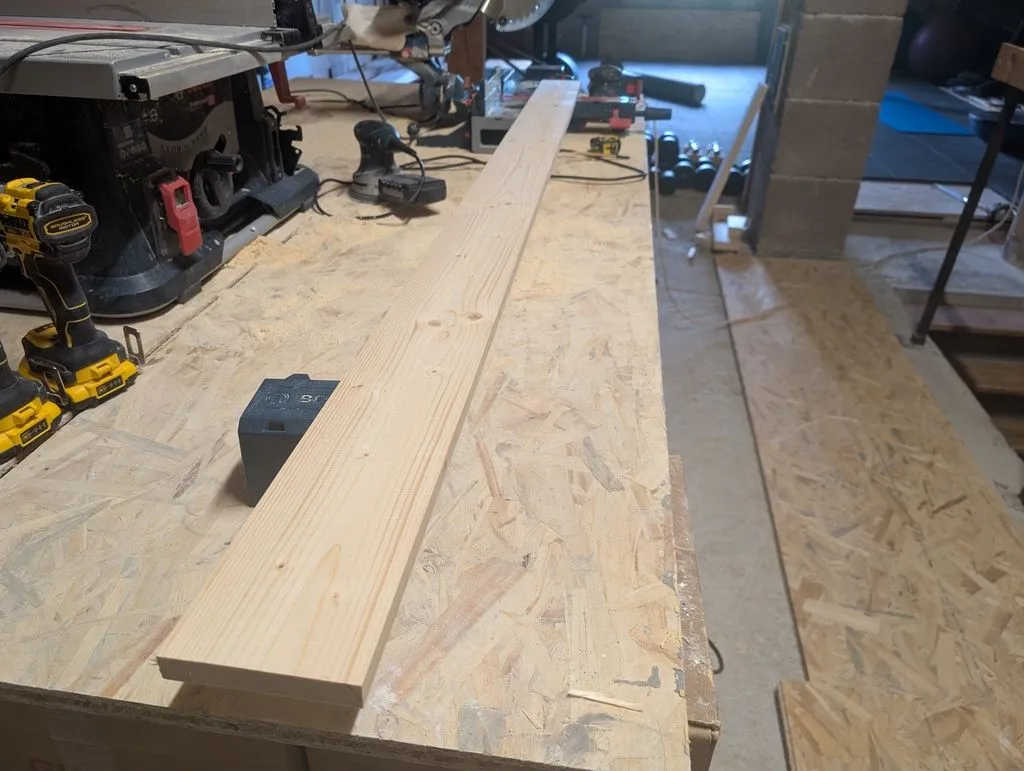
The 20 mm spruce stock from which we made the door casings.
We used a hand router and a coved bit to add a simple decorative profile to the casings.
Installing the first piece of casing on the main entry door.
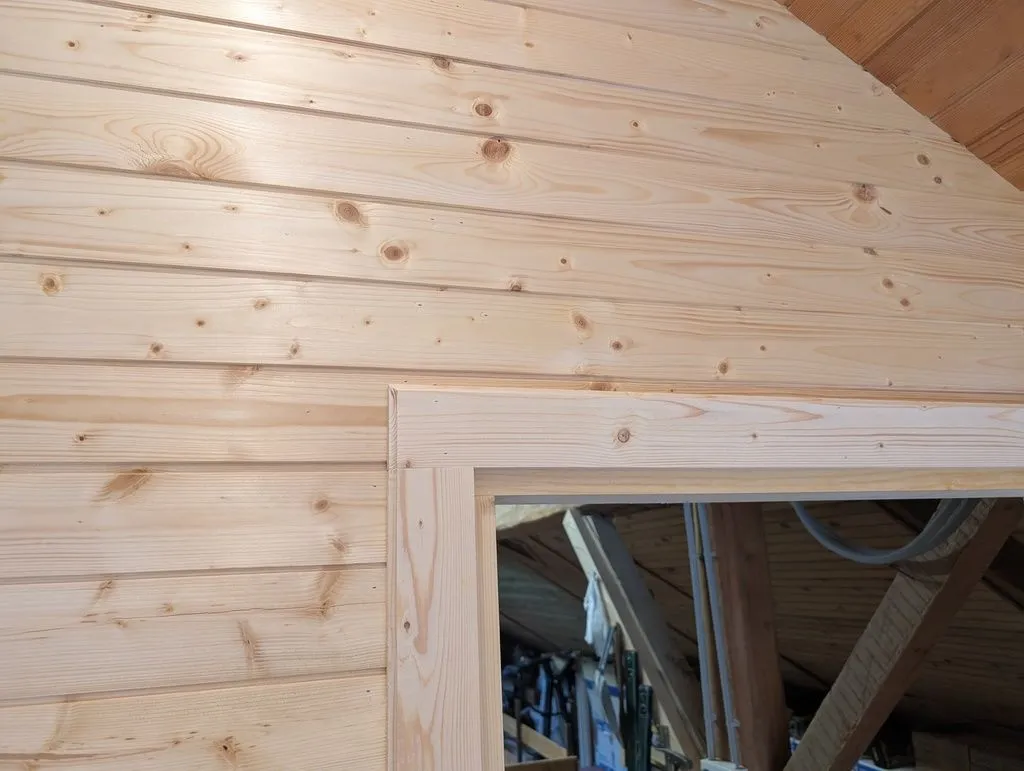
We used a simple butt joint to join the top and side casings.
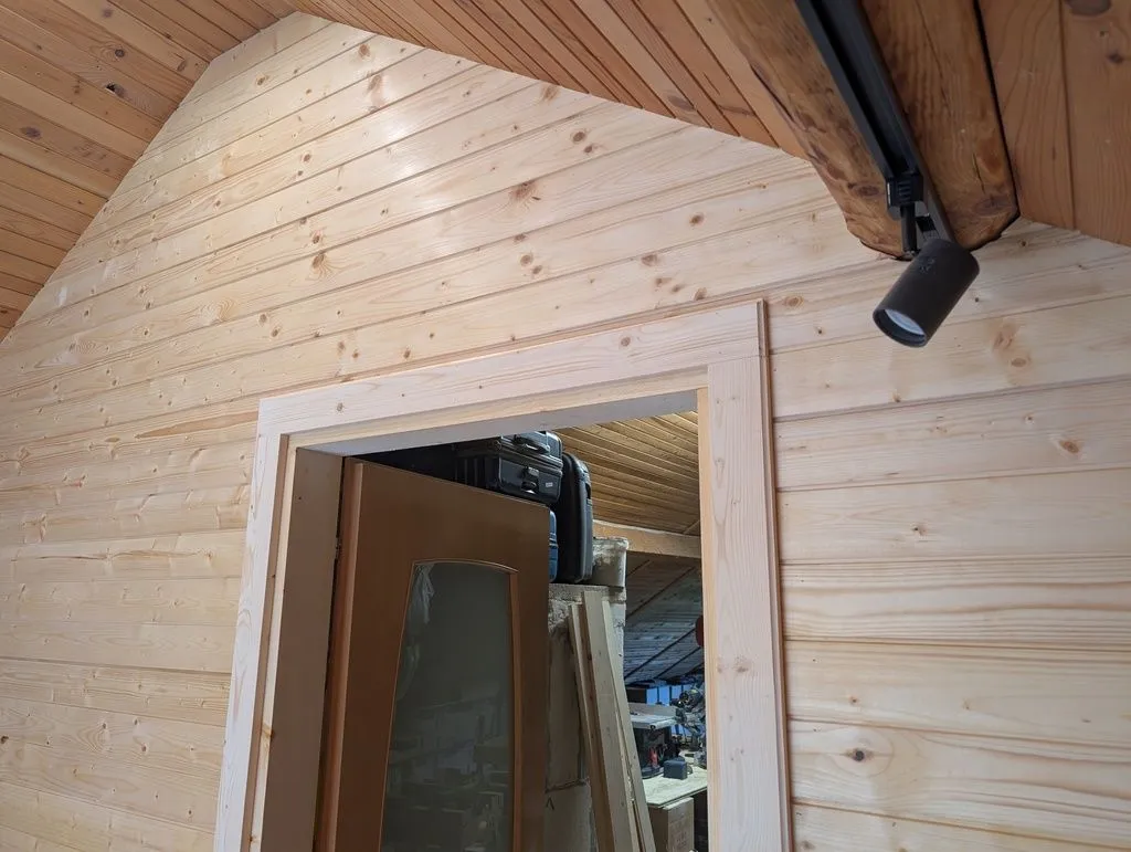
The installed casing on the inside of the main entry door. Similar casings are installed on the exterior side, and on the bathroom door.
The casings are attached with 18 gauge brad nails; the nail holes are filled with wood filler...
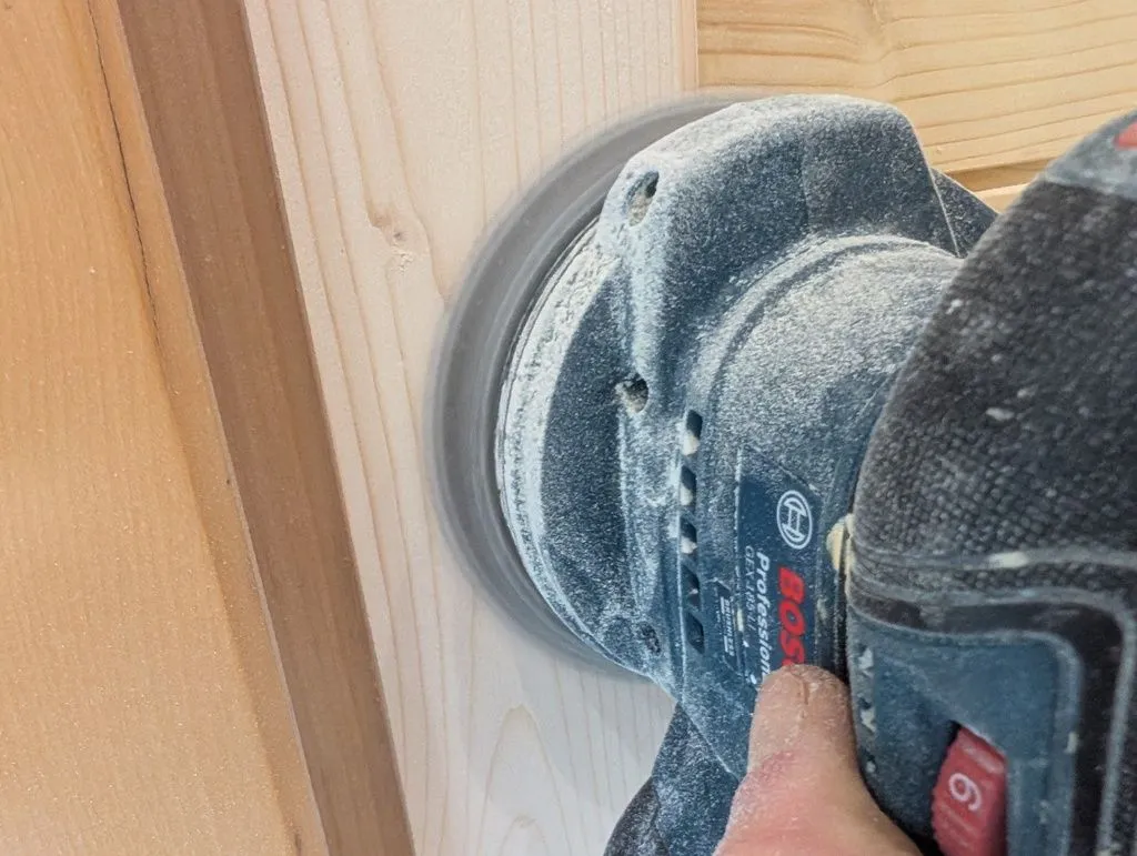
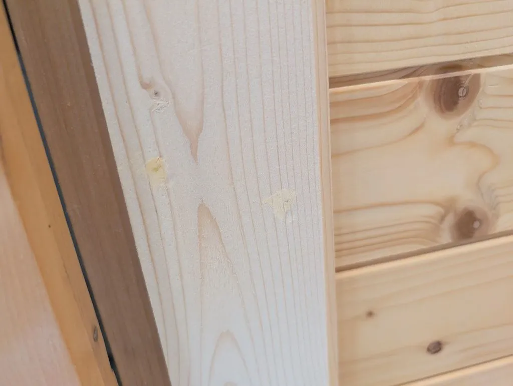
..and then sanded flush to remove any residual filler.
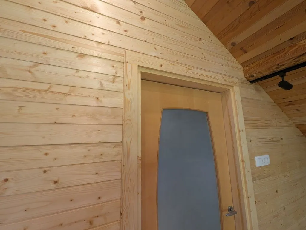
The completed casing on the entry door after finishing with linseed oil.
Finish carpentry: thresholds
We built two thresholds—one to cover to cover the butt joints at the main entry door and one to cover the gap between the main living space and sleeping nook (which I left intentionally for insurance, as expansion space to minimize buckling in the event of excessive expansion). The thresholds are made from the same spruce lumber as the tongue and groove wall finish, and are made from two pieces joined together on edge—I didn't have any flat stock wide enough to make the thresholds in one piece.
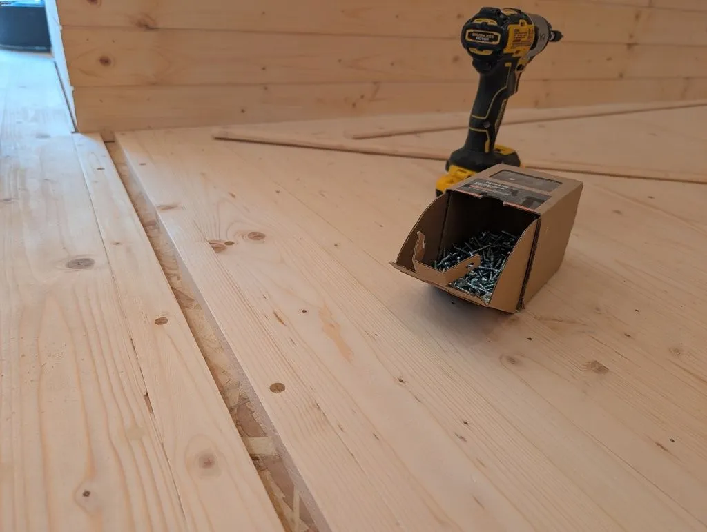
The expansion gap between the main living space and sleeping nook, which we would cover with a threshold.
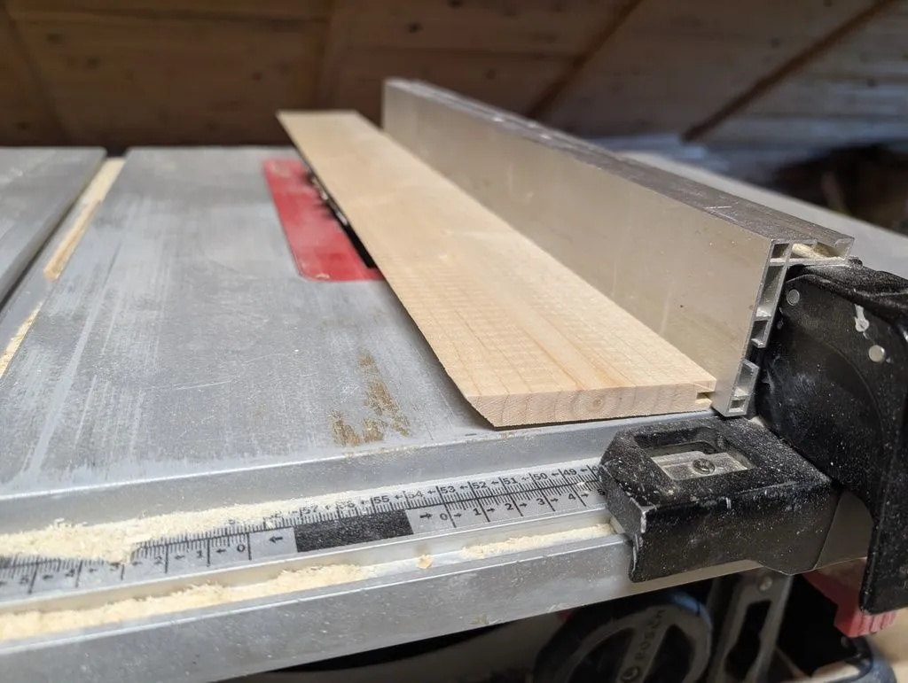
Shaping the threshold part 1: the end goal was a curved edge to match the profile of the arch of a human foot; I began by cutting a bevel on the table saw to get the rough shape.
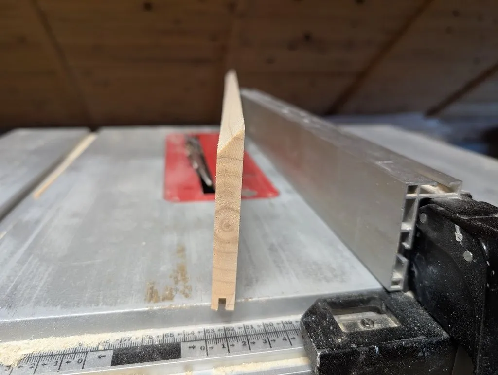
On the way to a curved edge—the temporary beveled edge made on the table saw.
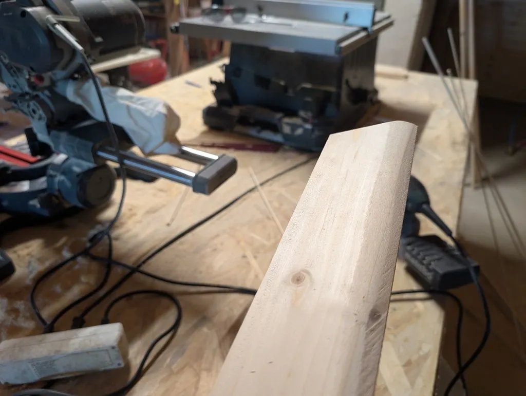
I then rounded out the beveled edge with an aggressive sanding disk on the angle grinder...
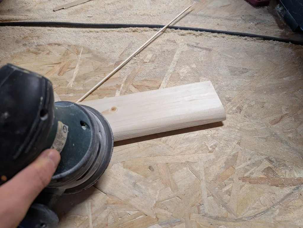
...and finally smoothed this out with an orbital sander to create a smooth rounded edge.
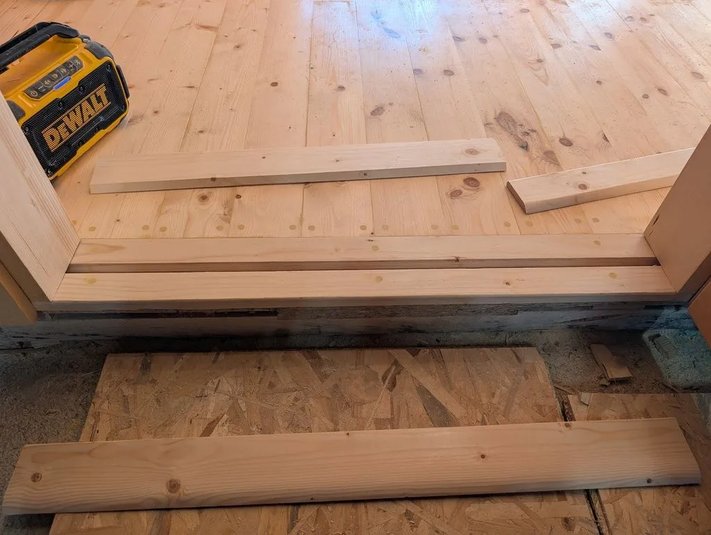
The first piece of the threshold, which would entirely span the gap in the floor, ready for installation.
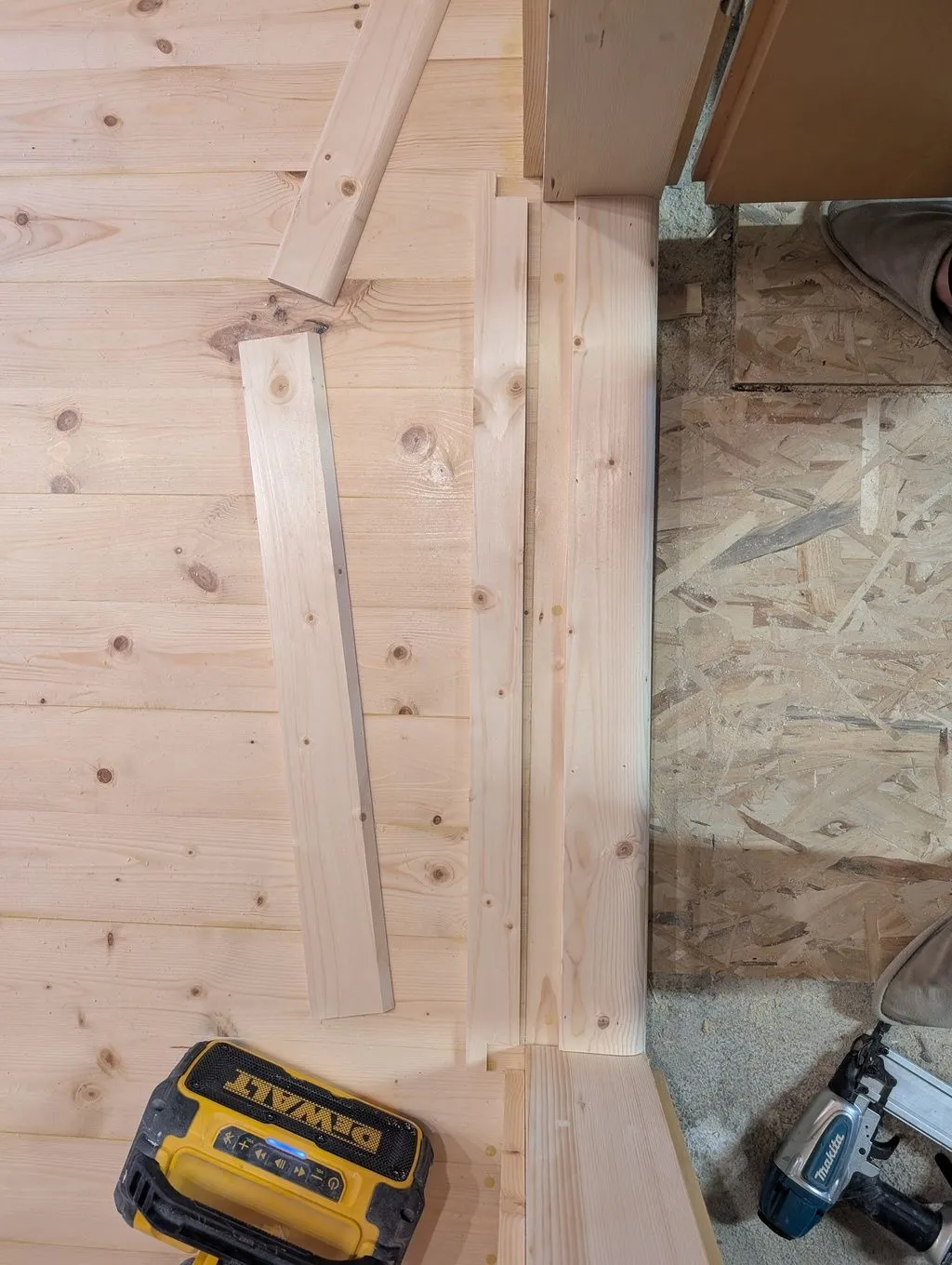
The second piece of the threshold, with ends notched to fit around the door jambs, ready for installation.
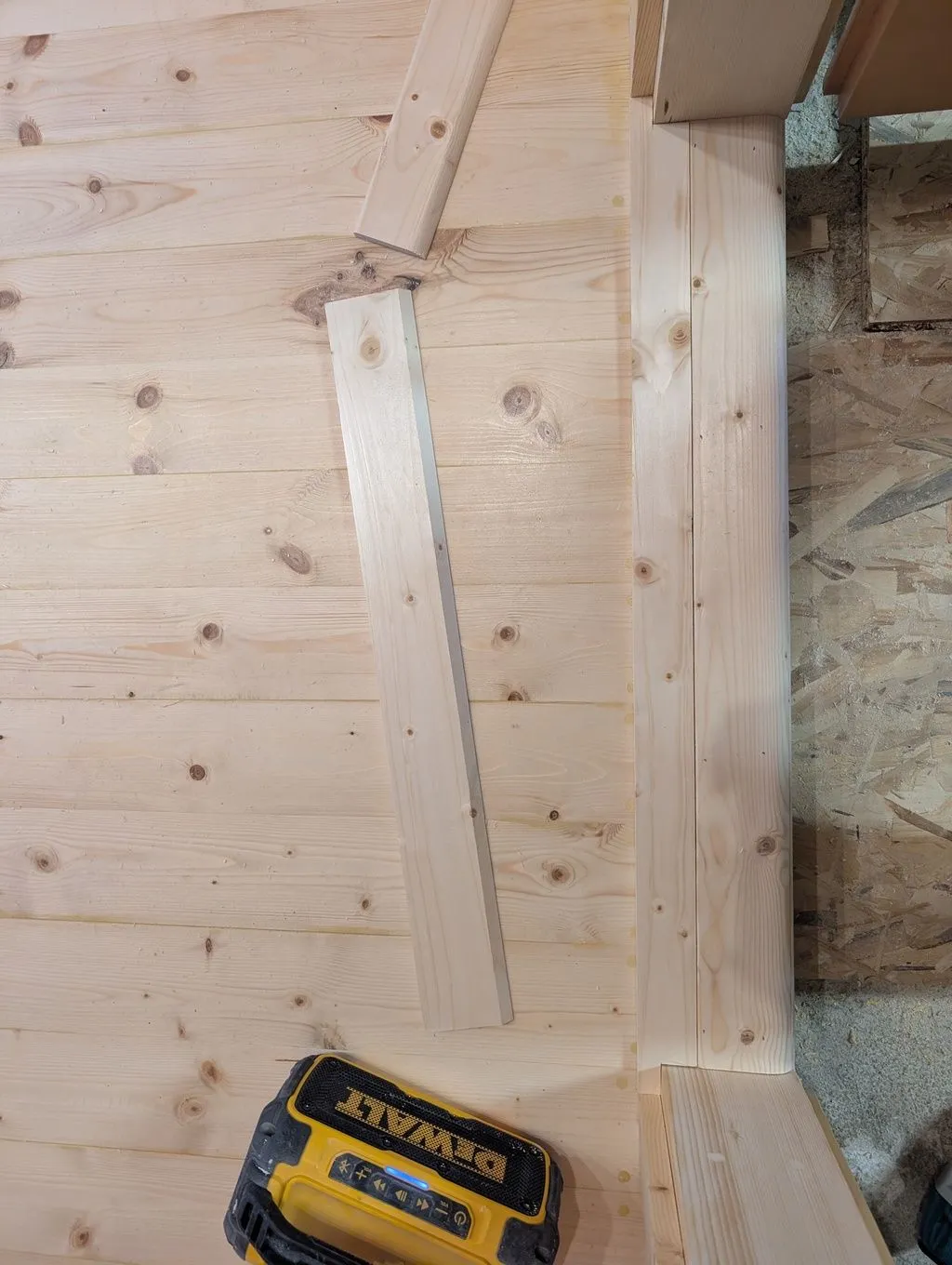
The second piece of the main entry threshold in place.
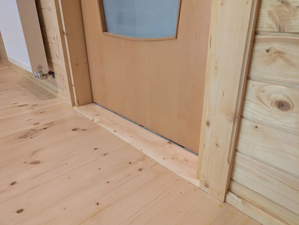
The main entry threshold after filling, sanding, and finishing.
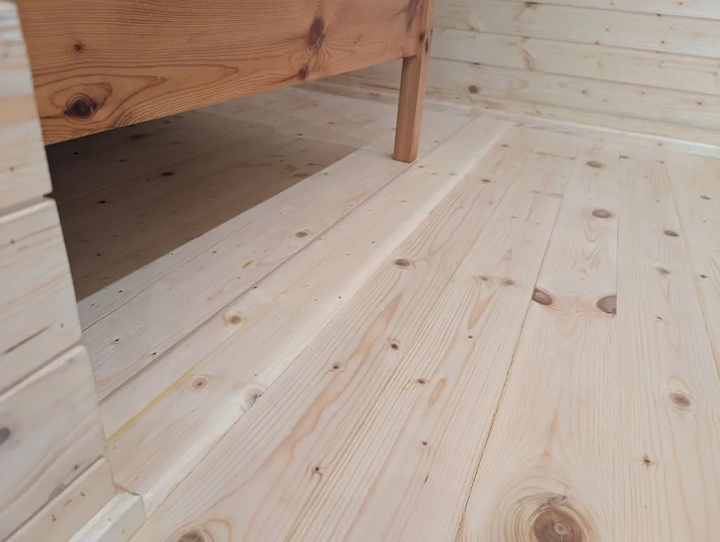
The threshold over the gap between the sleeping nook and living area, made with a analogous procedure as for the main entry threshold.