Electrical Panel Replacement
Investigating the panel before beginning the rewire and replacement.
Summary: This page documents replacing the electrical panel in our family's Ljubljana apartment.
My initial motivation was to install a residual current circuit breaker (RCCB) as a basic safety measure, but the panel had enough questionable traits beyond the lack of an RCCB that I opted for a full replacement—the details are covered in the following text.
The end result is more cramped than I would have liked—a consequence of reusing the existing cavity instead of cutting a new, larger cavity into into the masonry wall to free up space. But, crucially, I ended up with properly balanced circuits, residual current/ground fault protection, and a clear picture of what's going on in the panel.
Problems with the previous panel
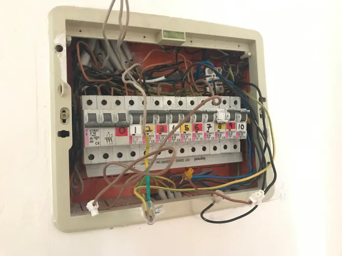
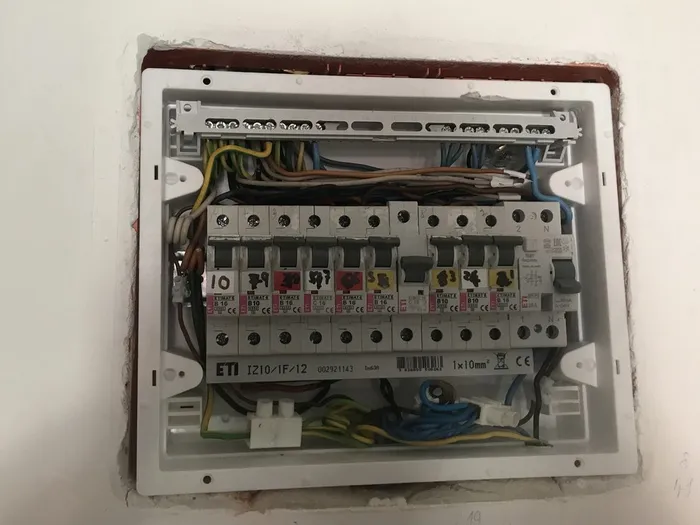
The original panel was visibly chaotic even to the casual observer, with a number of less-visible quirks described in the text below.
Initial status: Following the sacred electrician's tradition of talking shit on the existing work (not that I can claim to be an electrician, only a shit-talker), here are some of the, um, questionable characteristics I discovered and replaced in the original panel. Some are dangerous, some merely curiosities to chuckle at:
- No cover
- No neutral or ground busbars
- No ground fault protection
- Overly-stripped wire around connectors (read: exposed copper)
- An undersized 10 ampere main breaker
- Overloaded shared neutral wires
- A 3-phase main breaker and supply rail, even though I have one-phase supply
Following is a gallery of some of these problems in more detail.
Gallery: Problems with the original panel
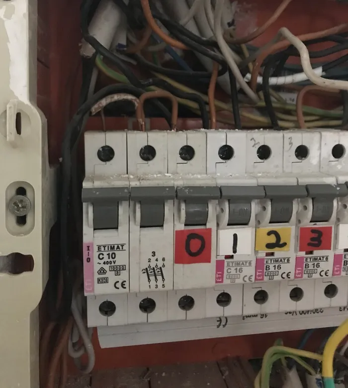
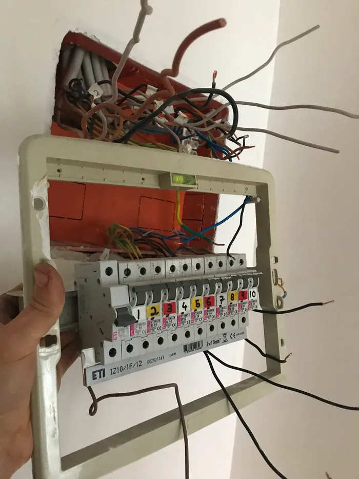
A renegade three-phase breaker...
The panel mysteriously used a three phase breaker—note the 400 V rating and three-terminal switching diagram. I say mysteriously, because I have only 1-phase supply!
Details
What's going on here? Did I originally have 3-phase power? (This is not unusual in Slovenia like it would be in the USA, even in residential settings.) Who knows...
A consequence: the main breaker was rated for 10 amperes (note the C10 marking)—this makes sense with 3-phase input, where the 10 A rating applies to each phase separately. But with my 1-phase input connected to a single terminal only (see the faintly visible thick black wire entering the third-from-left breakers from the top), the end result is a 10 A main breaker, which is smaller(!) than some of the 16 A breakers used for individual circuits, meaning the main breaker would trip before any individual circuit breaker, cutting power to the whole apartment if a single circuit overloads.
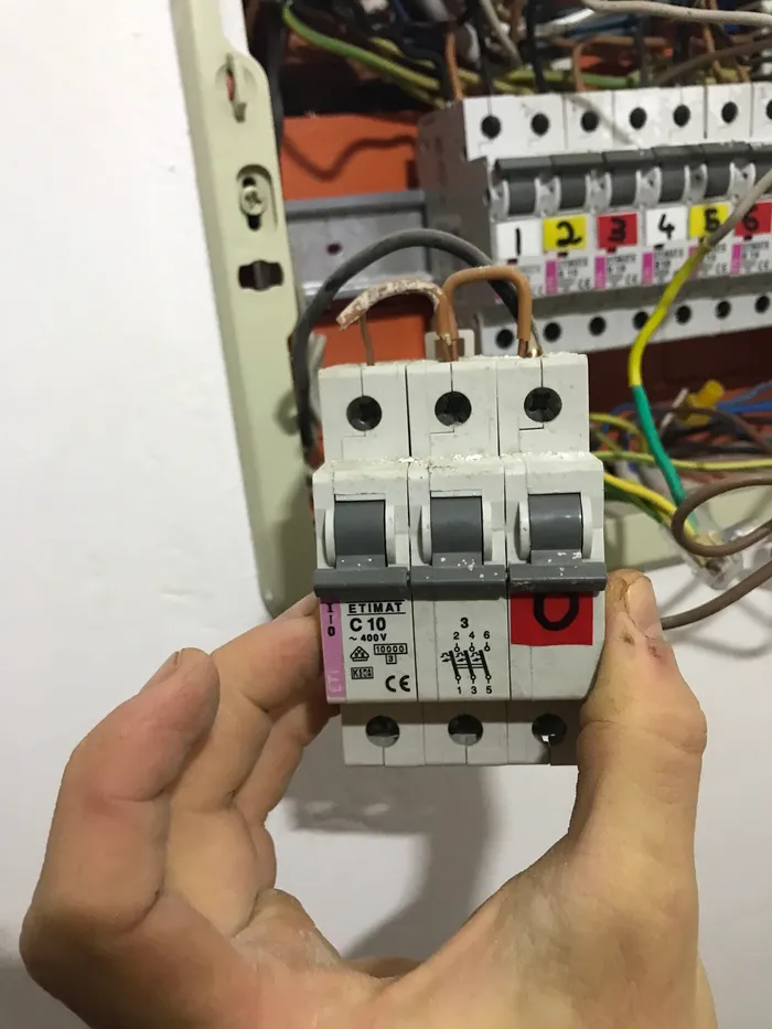
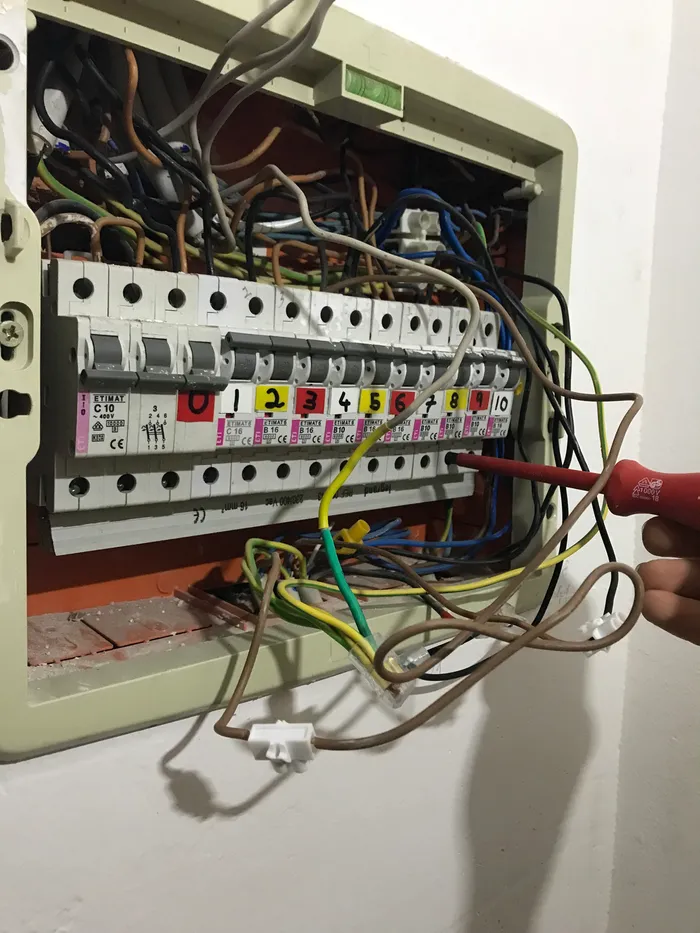
...made to work with jumper wires...
To distribute the single-phase supply (black wire entering the breaker on the top left) among the three-phase breaker's terminals, the original installer connected the terminals together with jumper wires (the two short brown wires in the top terminals), making for the funny-looking contraption shown above.
By the way, look at that brittle insulation and exposed copper!
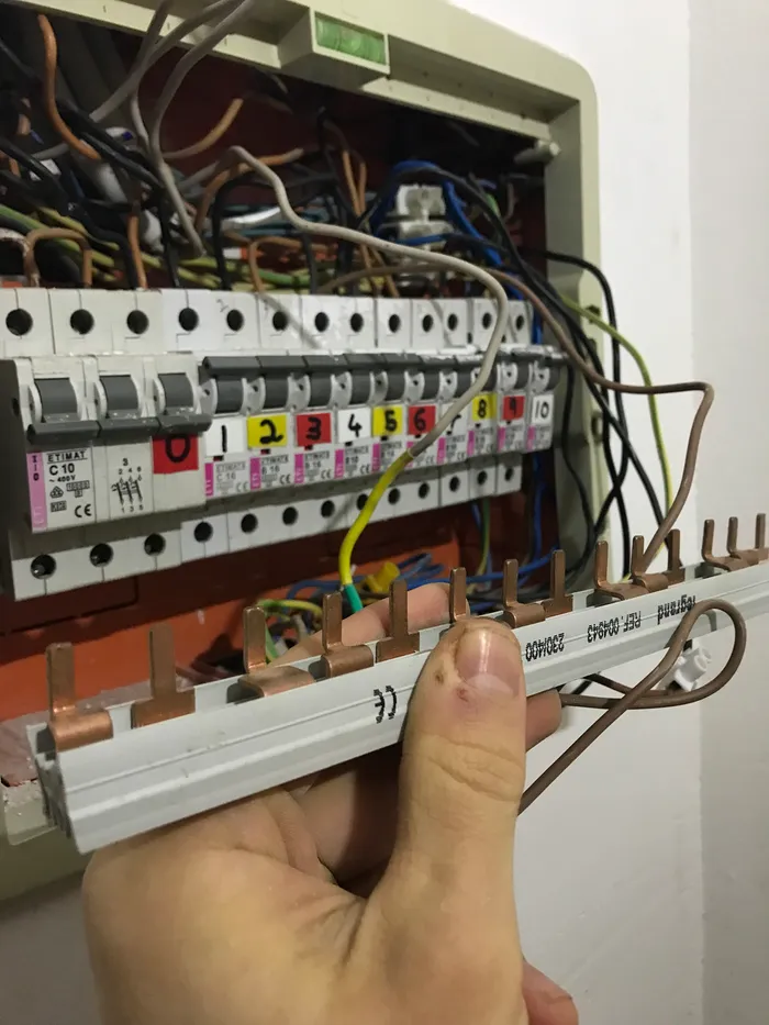
...because of needless use of a three-phase rail
The panel used a three-phase supply rail (the piece I am holding in my left hand, with the copper teeth sticking out), even though a one-phase rail would have worked fine for my one-phase supply.
Details
A three-phase rail like this has three electrically isolated pieces of copper (every third tooth is electrically connected), meant to keep three phases separate. A one-phase rail would have done just fine for my one-phase supply (and been about three times cheaper, and absolved the need for the hack with the jumper wires, since all the breakers would have been connected by the single piece of copper anyway).
Evidence points to my having a three-phase supply at one point, and that whoever did the conversion didn't bother to switch to appropriate one-phase material... or perhaps the original installer just had spare three-phase parts lying around he needed to get rid of? It's a mystery to me!
Busbars?
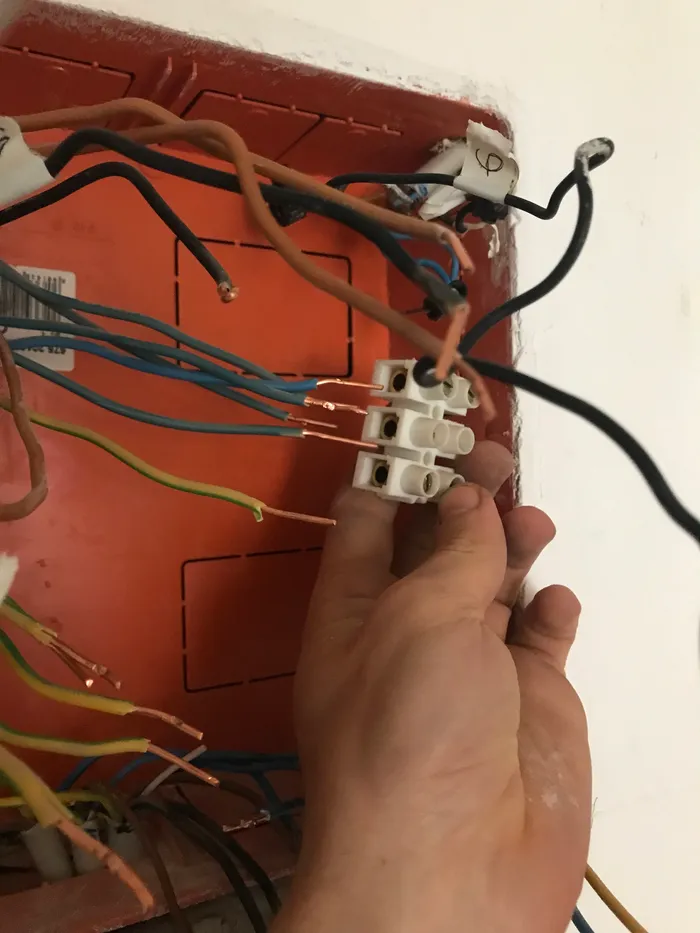
Who needs busbars?
Planning...
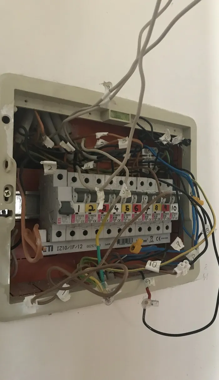
I used labels placed on the original wires (the numbers on the white electrical tape) to keep track of which wire was which when it came to disassembling the old panel.
| Wire | Destination |
|---|---|
| cable-1-black | Breaker 4 |
| cable-1-brown | Breaker 4 |
| cable-1-grey | Capped |
| cable-1-neutral | Neutral busbar |
| cable-1-ground | Ground busbar |
| cable-2-black | Breaker 10 |
| cable-2-neutral | Neutral busbar |
| cable-2-ground | Ground busbar |
| cable-3-black | Breaker 10 |
| cable-3-brown | Capped |
| cable-3-grey | Capped |
| cable-3-neutral | Neutral busbar |
| cable-3-ground | Ground busbar |
| ...and so on... | ...for all 11 cables... |
The goal here was ensure everything went smoothly once I began the rewire (i.e. you don't want to discover halfway through rewiring your panel, with the power cut and the freezer thawing, that you forgot to plan out were an extra cable should go).
Planning: Details
I first mapped out all wires entering the panel to see which circuits they corresponded to, then gave each cable and its constituent wires a label, which I used to keep track of which cable/wire would go where when rewiring.
I then re-planned circuits to:
- eliminate a few shared neutrals
- balance loads on breakers (e.g. previously the fridge and electric oven were on the same circuit breaker, while a separate circuit elsewhere consisted of only a single rarely-used outlet)
- ensure lights where on different breakers than outlets (standard practice so that if a breaker flips from an overloaded outlet the lights in the room stay on to let you figure out what's going on)
- and (within reason) make breakers near each other in the panel correspond to circuits near each other in the apartment.
Details: I'm a hopeless nerd, so the planning was done programmatically. Click to expand if you're curious.
I first mapped wires to the circuits they should supply, then mapped circuits to the breakers that should control them. Note the step of indirection here: I'm first thinking in terms of wires and circuits (when designing circuits in the planning stage), then in terms of circuits and breakers (during the actual boots-on-the-ground work of connecting wires to breakers).
I kept the wires-to-circuits mappings and circuits-to-breakers mappings in separate YAML dictionaries and used a Python program to handle the mapping between them programmatically.
The wires-to-circuits mapping looks like this...
# Which wires supply which circuits
wires:
  "cable-1-black": "Kitchen countertop outlets"
  "cable-1-brown": "Server"
  "cable-1-grey": null  # null wires are capped!
  "cable-1-neutral": "Neutral busbar"
  "cable-1-gnd": "Ground busbar"

  "cable-2": "Dining table outlets"
  "cable-2-neutral": "Neutral busbar"
  "cable-2-gnd": "Ground busbar"

  "cable-3-black": "Living room computer outlets"
  "cable-3-brown": null
  "cable-3-grey": null
  "cable-3-neutral": "Neutral busbar"
  "cable-3-gnd": "Ground busbar"

  # and so on for all 11 cables...
...the circuits-to-breakers looks like this...
# Which circuits should be controlled by which breakers
breakers:
  "MiniOffice": "breaker-1"
  "Kitchen lights": "breaker-2"
  "Entry door outlet": "breaker-3"
  "Server": "breaker-4"
  "Kitchen countertop outlets": "breaker-4"
  "Fridge and oven": "breaker-5"
  "Bathroom light and outlets": "breaker-6"
  "Washing machine": "breaker-7"
  "Boiler": "breaker-7"
  "Gym outlets": "breaker-8"
  "Partition wall outlets": "breaker-8"
  "Living room light": "breaker-9"
  "Living room computer outlets": "breaker-10"
"Dining table outlets": "breaker-10"With planning done I cut power and begin work (thankfully we have an extra fuse in series between the meter and our panel's main breaker, so I didn't have to work live).
The Rewire
Beginning disassembly by removing the old live busbar.
- disconnecting all the old wiring and removed the panel frame
- installing the new panel in the existing wall cavity and routing cables into the new panel
- installing ground, neutral, and hot busbars
- installing the RCCB (the RCCB also serves as the main breaker) and circuit breakers
- connecting cables/wires one by one to their destinations on the breakers and neutral/ground busbars
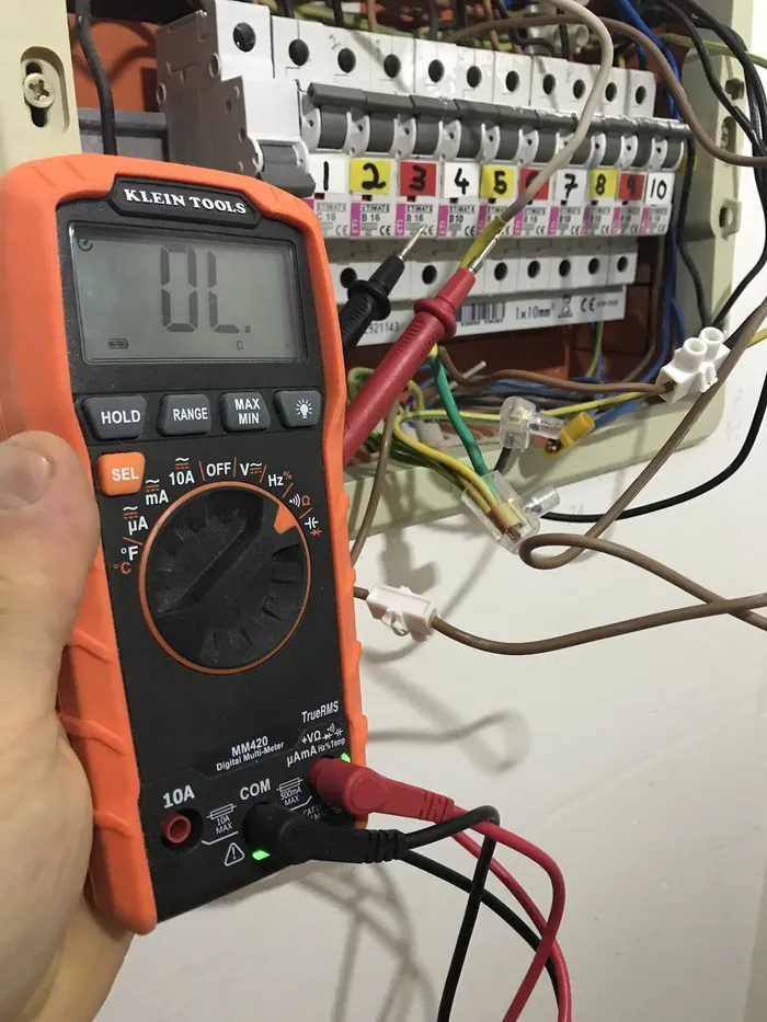
- finishing with standard de-energized continuity testing and energized voltage testing before fully energizing the circuits.
Routing all wires though a relatively cramped layout made the process slow, but everything went to plan, and all circuits functioned as expected under load. Below is a gallery of the process.
Gallery: The rewiring process
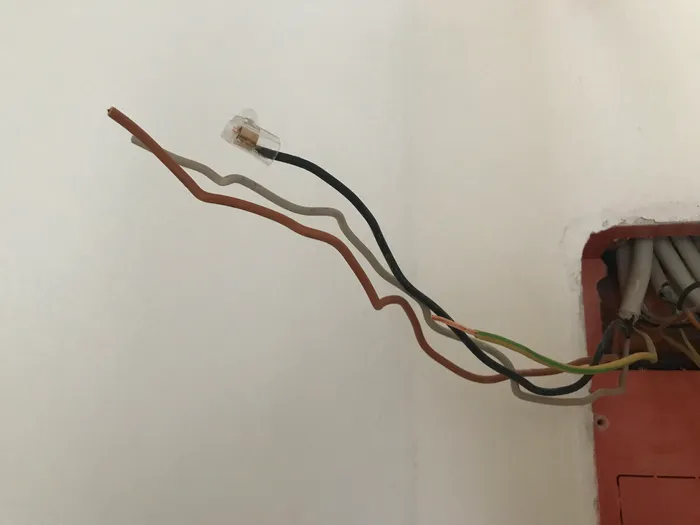
Power disconnected
I first temporarily disconnected and capped off the main supply (black line). The gray and brown lines are dead.
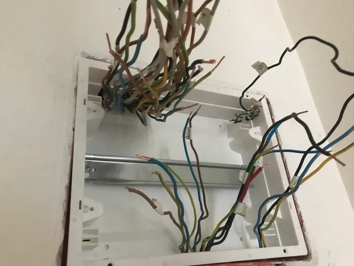
Old frame coming out
The old frame coming out after disconnecting the original wiring.
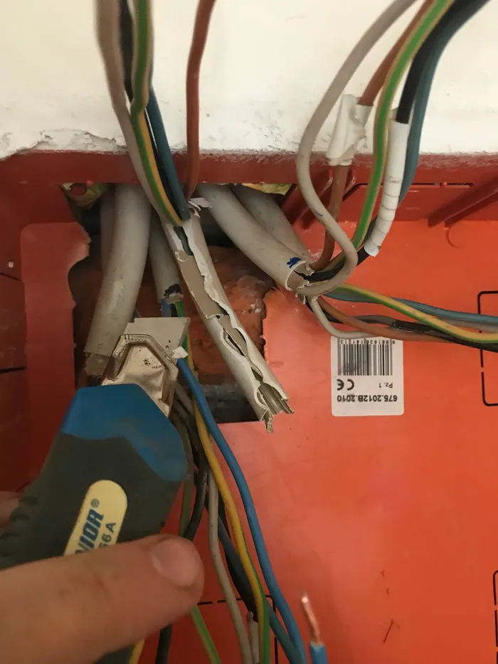
Cleaning up insulation
Some of the inbound cables still had the outer insulative sheath on. This would protrude into the new panel if left on, so I stripped it with a utility knife.
The new panel
A dry fit of the new panel enclosure with cables routed in but (clearly!) not yet organized. I reused the existing wall cavity.

Breakers and busbar installed
The breakers and busbars after installation. I reused the previous breakers, which were modern thermal/bimetallic MCBs in good condition.
Complete "rough-in"
The completed panel with wires routed and circuits connected. Next: testing the electrical connections, then leveling the panel and plastering in the gaps between the panel and surrounding walls.
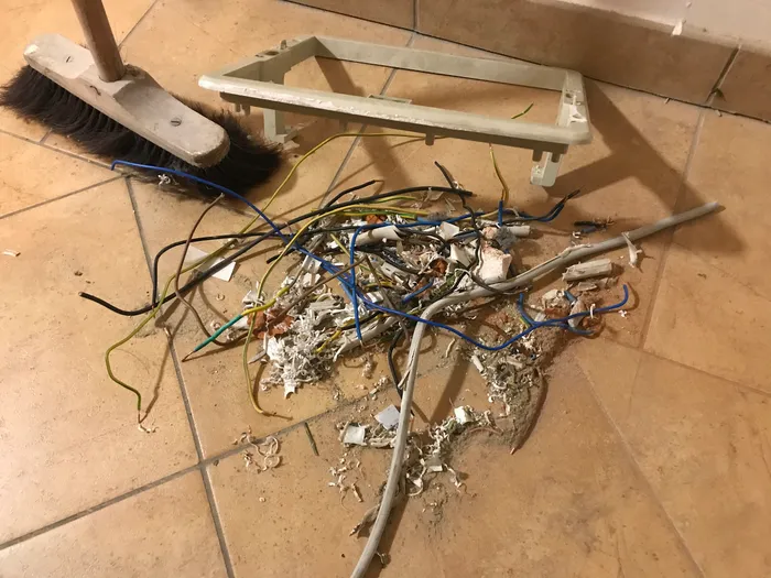
Clean-up
The stereotype, at least as I know if from the USA, is that electricians do not clean up after themselves. As mentioned earlier, I can hardly claim to be an electrician, so clean-up is appropriate.
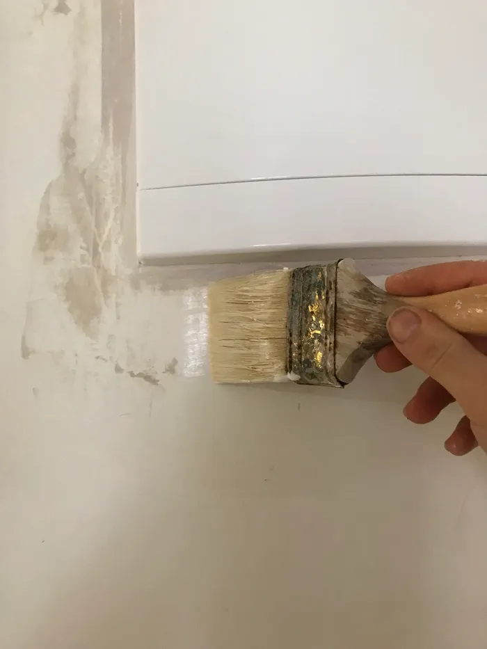
Finishing touches
After verifying electrical connections and ensuring all circuits worked as expected, I leveled the panel and filled the gaps between the panel and surrounding walls.
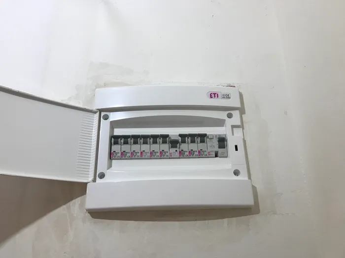
All done!
The completed panel.